Brake booster vacuum sensor diagnostic

a vacuum sensor and brake booster technology, applied in the field of brake booster vacuum sensor diagnostics, can solve problems such as ice to cycle in and out of dod mod

Active Publication Date: 2005-07-28
GM GLOBAL TECH OPERATIONS LLC
View PDF21 Cites 25 Cited by
  • Summary
  • Abstract
  • Description
  • Claims
  • Application Information

AI Technical Summary

Benefits of technology

[0008] In another feature, the diagnostic system further includes an error reduction fraction (ERF) calculator that determines an ERF based on the maximum error and the minimum error. The first comparator compares the ERF to a threshold to determine one of the pass status and the fail status. If the ERF is less than the threshold, the first comparator generates a fail status signal. If the ERF is equal to the threshold, the first comparator generates a pass status signal.
[0009] In still another feature, the diagnostic system further includes a second comparator that generates a first diagnostic enable signal based on an engine vacuum and a brake booster vacuum. The second comparator generates the first diagnostic enable signal if the brake booster vacuum is less than the engine vacuum.
[0010] In yet another feature, the diagnostic system further includes a third comparator that generates a second diagnostic enable signal based on a throttle position and a throttle position minimum. The third comparator generates the second diagnostic enable signal when the throttle position is less than the throttle position minimum. The monitor ceases monitoring of the maximum error and the minimum error if the third comparator ceases to generate the second diagnostic enable signal during the monitoring period.

Problems solved by technology

A faulty brake booster sensor may prevent the ICE from transitioning to the deactivated mode and / or may cause the ICE to cycle in and out of DOD mode.

Method used


Image

  • Brake booster vacuum sensor diagnostic
  • Brake booster vacuum sensor diagnostic
  • Brake booster vacuum sensor diagnostic

Examples


Embodiment Construction

[0016] The following description of the preferred embodiment is merely exemplary in nature and is in no way intended to limit the invention, its application, or uses. For purposes of clarity, the same reference numbers will be used in the drawings to identify similar elements.

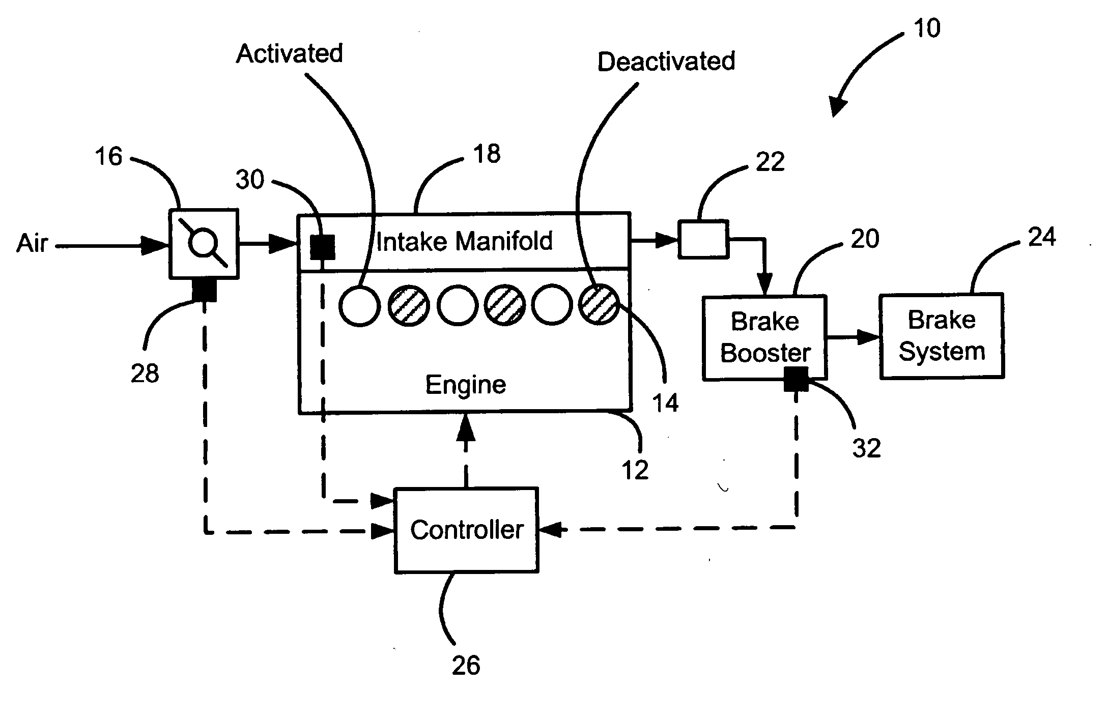
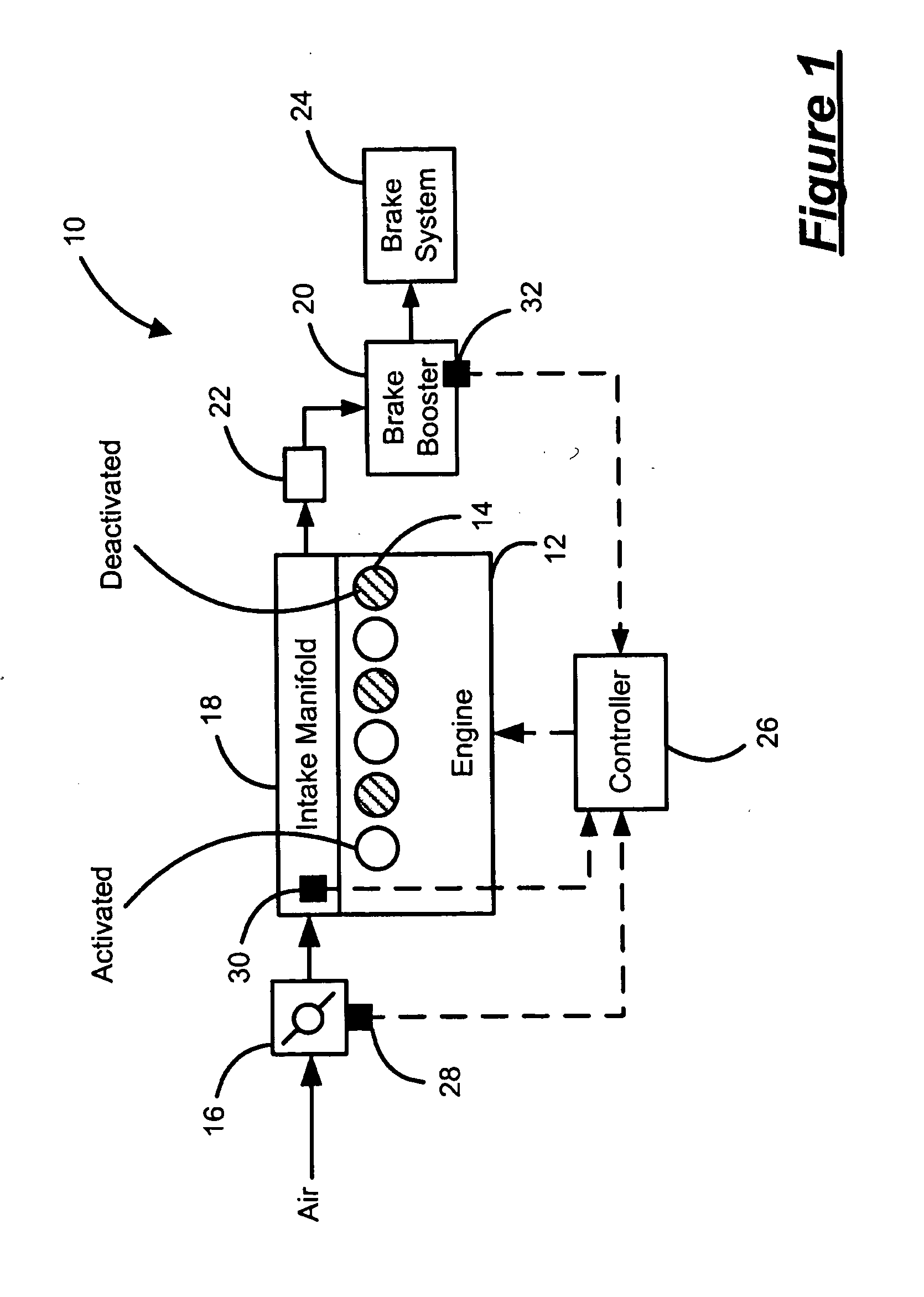
[0017] Referring now to FIG. 1, a vehicle 10 includes an engine 12. The engine 12 includes N cylinders 14 that are selectively deactivated during engine operation. Although FIG. 1 depicts six cylinders (N=6), it can be appreciated that the engine 12 may include additional or fewer cylinders 14. For example, engines having 4, 5, 6, 8, 10, 12 and 16 cylinders are contemplated. Air flows into the engine 12 through a throttle 16 and an intake manifold 18 and is combusted with fuel in the cylinders 14.

[0018] A brake booster 20 is in selective fluid communication with the engine 12 through a check valve 22. The brake booster 20 stores vacuum pressure supplied by the engine 12 to assist braking effort of a brake sys...


PUM


Abstract

A diagnostic system for a brake booster sensor includes a monitor that monitors a maximum error and a minimum error based on a brake booster sensor signal over a monitoring period. A first comparator determines one of a pass status and a fail status of the brake booster sensor based on the maximum error and the minimum error.

Description

FIELD OF THE INVENTION [0001] The present invention relates to vehicles with brake booster vacuum sensors, and more particularly to diagnostics for brake booster vacuum sensors. BACKGROUND OF THE INVENTION [0002] Vehicles such as automobiles and trucks include an internal combustion engine (ICE) that produces drive torque that accelerates the vehicle. The vehicle also includes a brake system that decelerates the vehicle. Brake systems include a brake booster that reduces braking effort by applying additional force to a master cylinder of the brake system. The brake booster uses a vacuum to apply force to the master cylinder. The brake booster vacuum is supplied by vacuum from the ICE. [0003] Some ICE's include engine control systems that deactivate cylinders under low load situations. For example, an eight cylinder engine can be operated using four cylinders to improve fuel economy by reducing pumping losses. This process is generally referred to as displacement on demand or DOD. As...

Claims


Application Information

Patent Timeline
Patent Type & Authority Applications(United States)
IPC IPC(8): B60T8/00B60T8/60B60T13/52B60T17/02B60T17/22G06F19/00
CPCB60T13/52F01L13/0005B60T17/02
Inventor LEHNER, CHAD W.HOOKER, DANIEL H.
Owner GM GLOBAL TECH OPERATIONS LLC
Why Eureka
Try Eureka