Phase-based ranging for backscatter RFID tags

Active Publication Date: 2014-07-03
DISNEY ENTERPRISES INC
View PDF1 Cites 21 Cited by
  • Summary
  • Abstract
  • Description
  • Claims
  • Application Information

AI Technical Summary

Benefits of technology

[0007]One embodiment of the present disclosure is a method of performing phase-based ranging techniques. The method includes estimating a plurality of first distances between a RF tag and an RF tag reader using a continuous-wave (CW) ranging technique and estimating a plurality of second distances between the RF tag and the RF tag reader using a multi-frequency continuous-wave (MFCW) ranging technique. The method includes performing spatial averaging based on the pluralities of first and second distances to mitigate the effects of an error associated with the plurality of second distances.
[0008]Another embodiment of the present disclosure is a RF tag reader. The tag reader includes an antenna and CW logic configured to estimate a plurality of first distances between a RF tag and the antenna using a CW ranging technique and MFCW logic configured to estimate a plurality of second distances between

Problems solved by technology

Conventional ranging techniques, such as received signal strength (RSS) for either active or passive RF tags, work over relatively large areas but suffer from poor accuracy.
Time of flight or frequency modulated continuo

Method used


Image

  • Phase-based ranging for backscatter RFID tags
  • Phase-based ranging for backscatter RFID tags
  • Phase-based ranging for backscatter RFID tags

Examples


Embodiment Construction

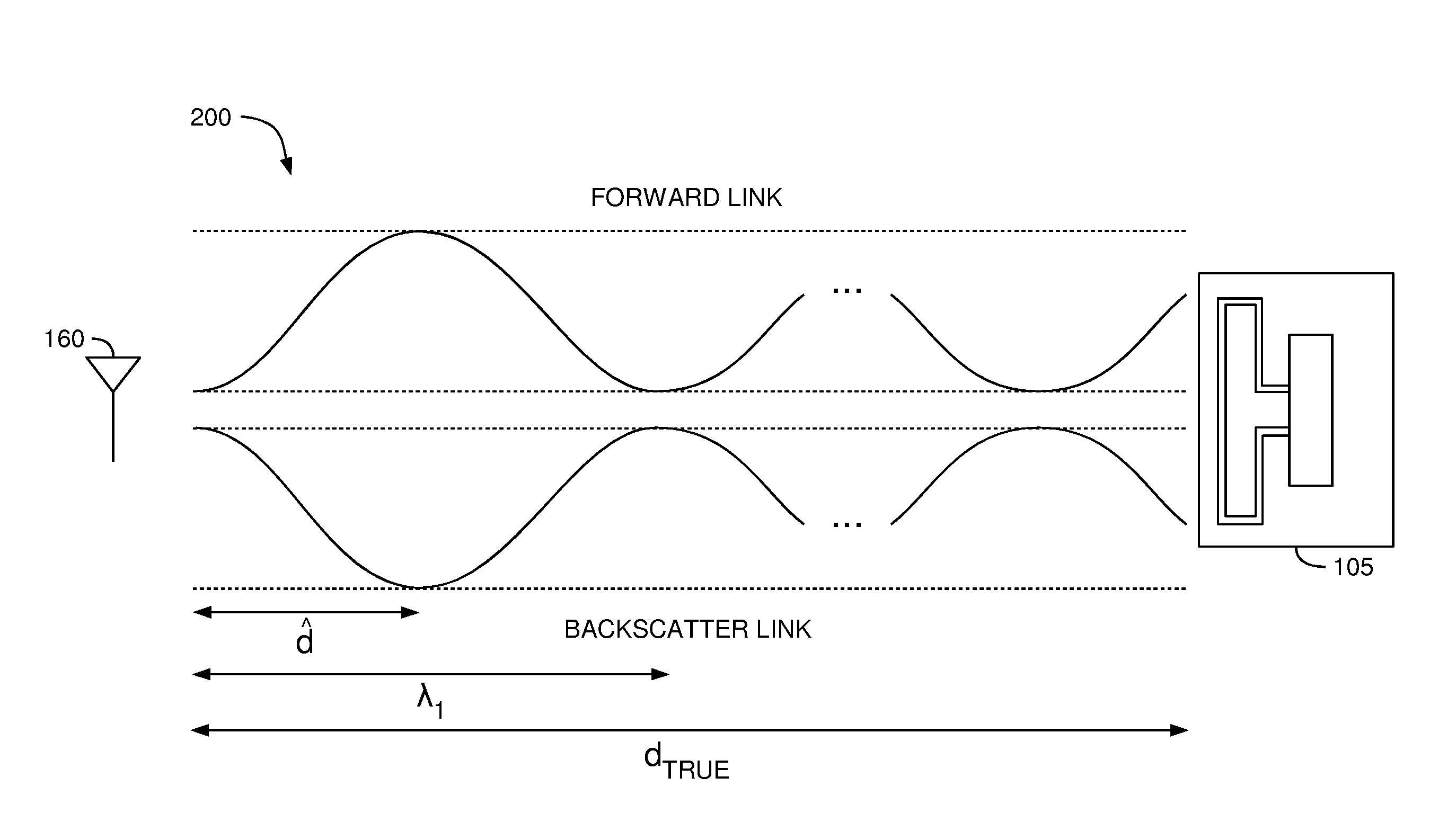
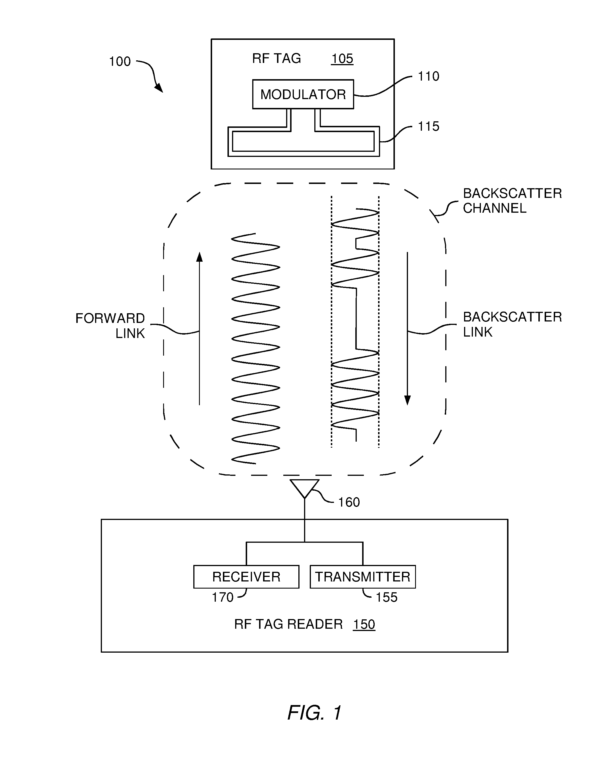
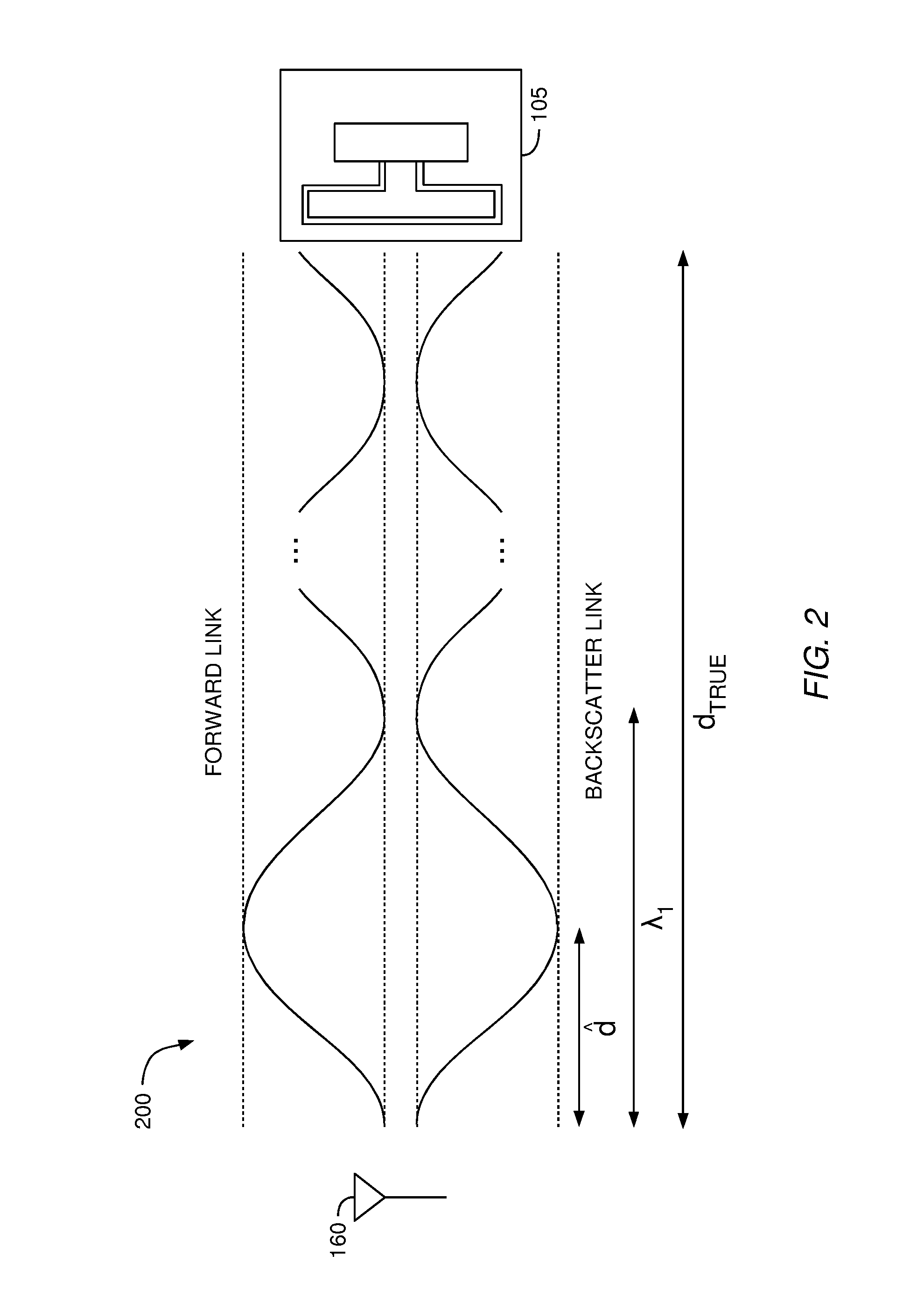
[0019]Identifying a distance between a RF tag and a receiver antenna of a RF tag reader (referred to herein as a “separation distance”) may include combining different phase-based ranging techniques. However, the different ranging techniques come with different advantages and disadvantages. Continuous-wave (CW) radar offers up to millimeter precision but suffers from cycle ambiguity (i.e., the measured distance is based on a wrapped phase rather than an unwrapped phase). Multi-frequency continuous-wave (MFCW) radar, on the other hand, estimates the separation distance using the difference between two wrapped phases, which results in a distance measurement that does not have a cycle ambiguity as long as the distance is less than the MFCW ambiguity distance. However, the MFCW estimated distance may be too inaccurate for certain uses. Instead of relying on only one of the ranging techniques, in one embodiment, the CW and MFCW techniques are used in tandem. Specifically, the tag reader ...


PUM


Abstract

A RF tag reader may use spatial averaging to compensate for the limitations of performing multi-frequency continuous-wave ranging (MFCW) in a bandwidth-limited environment. Although MFCW provides an estimate of the separation distance between a RF tag and the tag reader with errors that vary widely, the error values form a pattern based on the separation distance. That is, as the separation distance increases or decreases, the error values oscillate between maximum and minimum values centered on the correct separation distance. Accordingly, in one embodiment, the receiver uses spatial averaging to average out this oscillating error (e.g., the maximum errors are counter-balanced by the minimum errors). The more accurate, spatially-averaged MFCW estimate may then be used to resolve the cycle ambiguity in continuous-wave ranging to identify the separation distance between the RF tag and the tag reader.

Description

BACKGROUND[0001]1. Field of the Invention[0002]Embodiments presented in this disclosure generally relate to identifying a location of an RF tag and, more specifically, to determining a range of the tag using continuous wave radar.[0003]2. Description of the Related Art[0004]Typical radio frequency identification (RFID) tags or RF tags include a microprocessor functionally connected to an antenna. The microprocessor stores and processes relevant data that may include unique data for identifying a specific item associated with the RF tag. The microprocessor also modulates a radio frequency (RF) signal that is transmitted or backscattered via the antenna. An external tag reader captures the data signal transmitted by the RF tag.[0005]RF tags can be classified as “active” or backscatter devices. Active tags use an internal power source to actively transmit a modulated signal to the tag reader. Backscatter tags, in contrast, do not actively transmit modulated signals to the tag reader bu...

Claims


Application Information

Patent Timeline
IPC IPC(8): G01S13/84
CPCG01S13/84
Inventor ZHOU, CHENMINGGRIFFIN, JOSHUA D.
Owner DISNEY ENTERPRISES INC
Why Eureka
Try Eureka