Communication apparatus, communication method, and communication system

a communication apparatus and communication system technology, applied in the field of communication apparatus, communication method, and communication system, can solve the problems of difficult monitoring transmission data at the same time when a communication apparatus transmits, communication apparatus cannot isolate communication data, and communication apparatus cannot utilize any medium, so as to improve the substantial communication throughput, eliminate overhead, and efficient use of frame format

Active Publication Date: 2005-07-28
PALMIRA WIRELESS AG
View PDF14 Cites 99 Cited by
  • Summary
  • Abstract
  • Description
  • Claims
  • Application Information

AI Technical Summary

Benefits of technology

[0011] The present invention is directed to provide a communication apparatus, a communication method, and a communication system which enable coexistence of an existing apparatus, and which can eliminate an overhead due to transmission of a plurality of frames by efficient use of a frame format and can improve a substantial communication throughput.

Problems solved by technology

In the case where two or more communication apparatuses transmit communication data by utilizing the same media at the same time, there can occur an event (collision) that a receiving communication apparatus cannot isolate communication data.
On the other hand, although a communication apparatus having a transmitting request exists, there can occur an event that a medium is not utilized by any communication apparatus.
However, in particular, in wireless communication, it is difficult to monitor transmission data at the same time when a communication apparatus transmits data.
Here, even if a higher data rate has been successfully achieved with respect to a physical layer, there is a problem that a substantial communication throughput cannot be improved.
That is, in the case where a higher data rate of the physical layer has been achieved, a format of a PHY frame is no longer effective.
It is considered that an overhead caused by this problem inhibits improvement of throughput.
However, a length of a frame of a physical layer including the MAC frame cannot be set to about 4 Kbytes or more because of a restriction on a conventional physical layer.
Therefore, large restriction applies to improvement of efficiency.
Even if a frame of a physical layer can be increased in length, there occurs a problem that error tolerance is lowered.

Method used


Image

  • Communication apparatus, communication method, and communication system
  • Communication apparatus, communication method, and communication system
  • Communication apparatus, communication method, and communication system

Examples


first embodiment

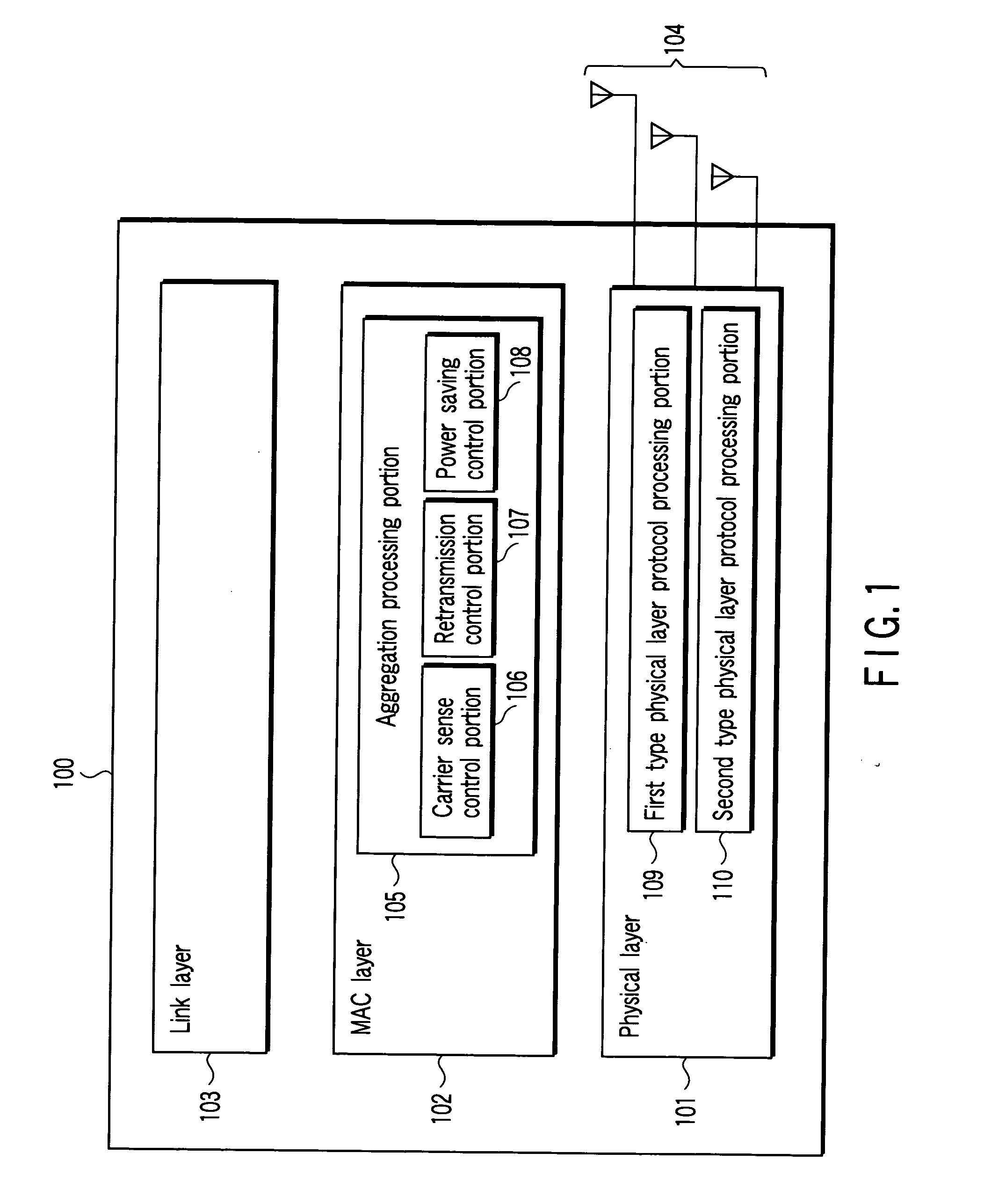
[0033]FIG. 1 is a block diagram depicting a configuration of a communication apparatus according to a first embodiment of the present invention. This communication apparatus 100 is provided as an apparatus which communicates with another communication apparatus via a wireless link. This communication apparatus includes processing units 101, 102, 103 which correspond to a physical layer, a MAC layer, and a link layer, respectively. These processing units are implemented as an analog or digital electronic circuit according to packaging or as a firmware executed by a CPU incorporated in an LSI. An antenna 104 is connected to the processing unit 110 of a physical layer (hereinafter, an expression of “processing unit” is omitted). The MAC layer 102 includes an aggregation (integration) processing portion 105 according to embodiments of the present invention. The aggregation processing portion 105 comprises at least a carrier sense control portion 106 in the first embodiment. A retransmis...

second embodiment

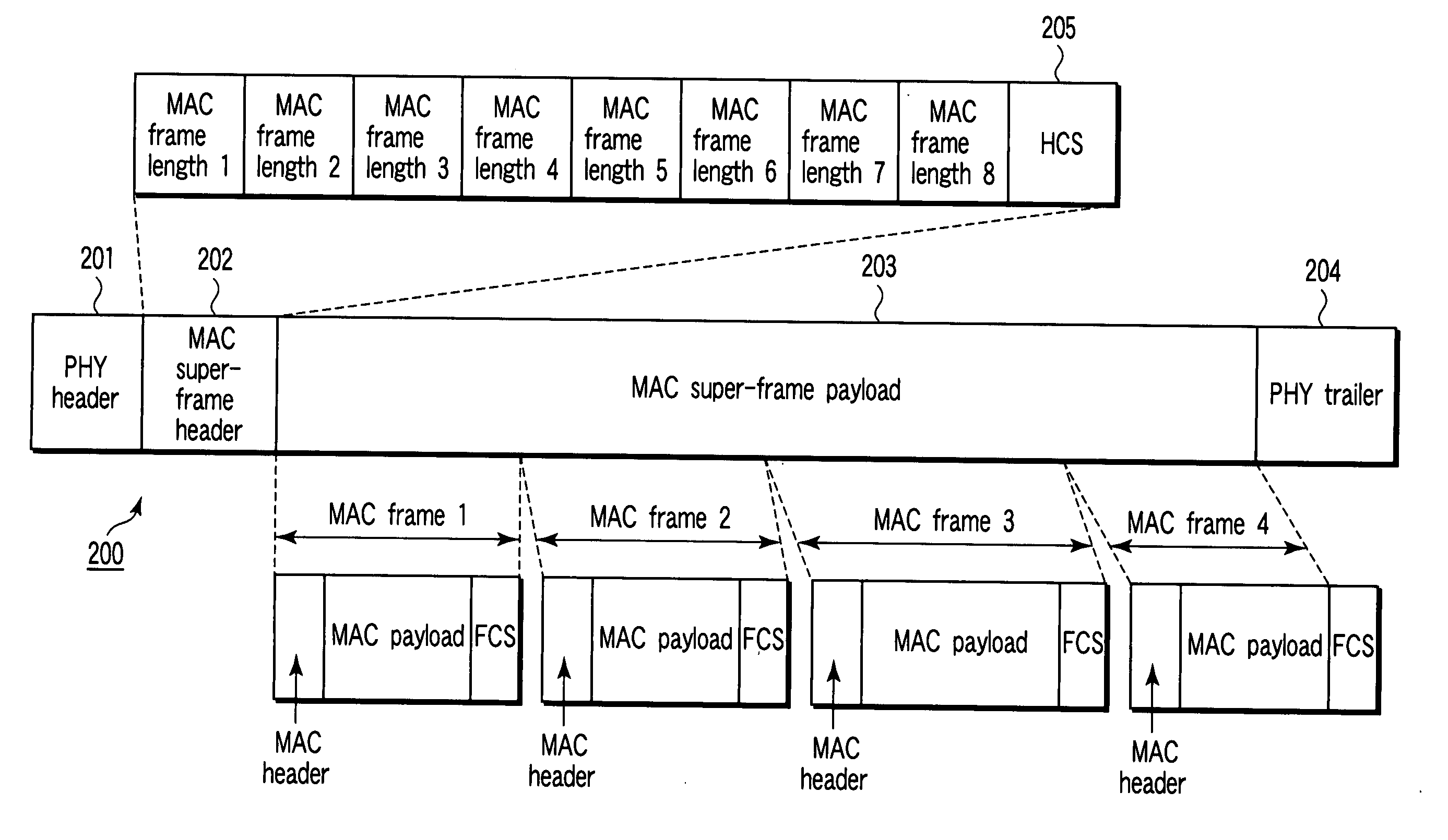
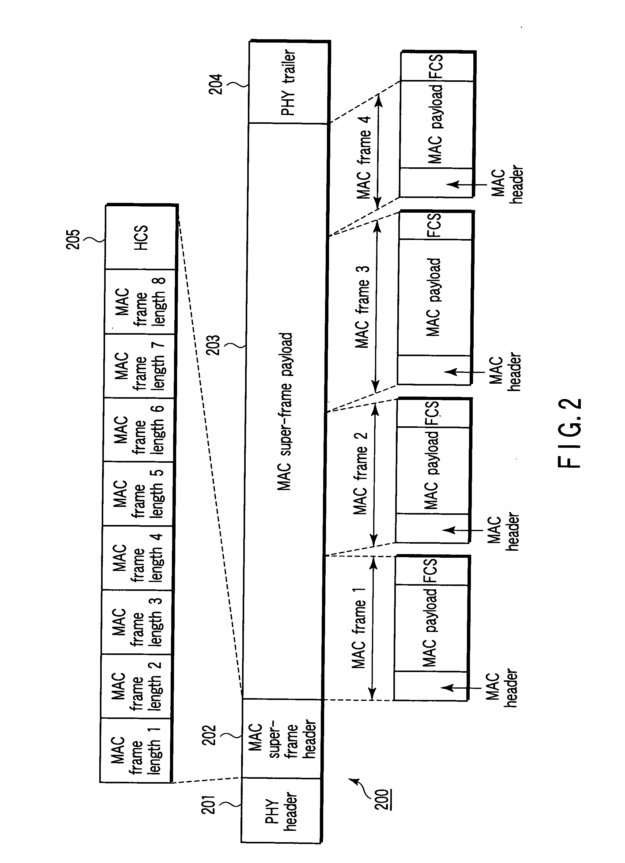
[0072] A second embodiment of the present invention relates to power saving control. FIG. 10 is a view illustrating power saving control according to the second embodiment of the invention. According to the present embodiment, the transmitting communication apparatus 1 and the receiving communication apparatus 2 being in communication are controlled so as not to be switched to a power saving state, and a communication apparatus which does not relate to communication can be controlled so as to be switched to the power saving state.

[0073] At a time point when the communication apparatus 3 recognizes any of the MAC frames included in the MAC super-frame included in the second type PHY frame is recognized to be correct by the FCS, the communication apparatus 3 recognizes that there is no need for carrying out reception or transmission over a duration in which NAV set by the communication apparatus 3 itself terminates, and starts a power saving operation from that time point. However, i...

third embodiment

[0076] A third embodiment of the present invention relates to retransmission control. From the viewpoint of communication fairness or QoS (Quality Of Service), it is preferable that retransmission be controlled to limit consecutive communication to the same terminal. FIG. 11 is a view showing a transmission managing table for use in retransmission control according to the third embodiment of the invention. In this transmission managing table, a Sliding Window is expressed. For convenience of explanation, the transmission managing table expresses a full history of transmission and reception including retransmission. However, in actual implementation of a communication apparatus, there is no need for storing the full history described here.

[0077] Consider a state in which the same transmitting communication apparatus continuously transmits a MAC frame (MPDU) to the same receiving communication apparatus prior to communication of another frame. In order to avoid biases assignment of t...


PUM


Abstract

A physical frame is constructed, the physical frame including a medium access control super-frame payload which in turn includes a plurality of medium access control frames. With respect to the constructed physical frame, virtual carrier sense information is set in the plurality of medium access control frame so that a result of carrier sense is identical to another by virtual carrier sense based on the plurality of medium access control frames in the medium access control super-frame payload. The physical frame in which the virtual carrier sense information has been set is transmitted to a destined communication apparatus.

Description

CROSS-REFERENCE TO RELATED APPLICATIONS [0001] This application is based upon and claims the benefit of priority from prior Japanese Patent Application No. 2004-004847, filed Jan. 9, 2004, the entire contents of which are incorporated herein by reference. BACKGROUND OF THE INVENTION [0002] 1. Field of the Invention [0003] The present invention relates to a communication apparatus, a communication method, and a communication system for making a media access control based on carrier sense information contained in a physical layer and carrier sense information contained in a MAC layer. [0004] 2. Description of the Related Art [0005] A Media Access Control (MAC) is to determine how a plurality of communication apparatuses making communication by sharing the same media utilize media to transmit communication data. In the case where two or more communication apparatuses transmit communication data by utilizing the same media at the same time, there can occur an event (collision) that a re...

Claims


Application Information

Patent Timeline
Patent Type & Authority Applications(United States)
IPC IPC(8): H04L12/28H04L12/413H04L12/46H04L12/66H04W28/00H04W28/06H04W84/12
CPCH04L12/413H04L12/46H04W28/065H04W28/06H04W84/12H04L12/66H04W52/0203Y02D30/70H04L2101/622H04L1/1607H04L69/324H04W74/0816H04L1/1614H04L5/0055H04L69/22H04L69/323H04W28/14H04L5/0044Y02B70/30
Inventor TAKAGI, MASAHIRONISHIBAYASHI, YASUYUKIUTSUNOMIYA, YORIKO
Owner PALMIRA WIRELESS AG
Why Eureka
Try Eureka