Voice packet loss concealment device, voice packet loss concealment method, receiving terminal, and voice communication system

a voice packet and concealment device technology, applied in the field of voice packet loss concealment devices, can solve the problems of voice packets transmitted regularly from the transmitting terminal to the receiving terminal being delivered irregularly, affecting the transmission band, and affecting the transmission of voice packets, so as to improve the subjective deterioration of auditory naturalness and continuity caused by voice packet loss

Inactive Publication Date: 2005-07-28
FUJITSU LTD
View PDF4 Cites 43 Cited by
  • Summary
  • Abstract
  • Description
  • Claims
  • Application Information

AI Technical Summary

Benefits of technology

[0052] Thus, with the arrangement described above, the waveforms of the loss concealment packet and the voice packet received normally after the packet loss are connected smoothly, which allows both abnormal noi

Problems solved by technology

Here, since IP network is a best effort type one, the transmission band of voice packets transmitted from a transmitting terminal to a receiving terminal is not assured and there may occur a transmission delay fluctuation due to, for example, congestion in transmission channel.
That is, voice packets transmitted regularly from the transmitting terminal may arrive at the receiving terminal irregularly.
Therefore, voice packet delay may cause the loss or lack of a voice packet to be received, resulting in the deterioration of voice quality.
However, an excessive increase in the capacity of the receive-packet buffer 50 for absorbing transmission delay causes an increase in the accumulation time in the receive-packet buffer 50 and thereby call delay, resulting in a trouble in the interactive conversation.
Also, voice packets having a transmission delay more than the capacity of the receive-packet buffer 50 are too late for readout.
Consequently, the voice reproducing device 51 reproduces voice with some voice packets being lost, resulting in the deterioration of voice quality.
In addition to transmission delay fluctuation, there may also occur a voice packet loss in an IP network.

Method used


Image

  • Voice packet loss concealment device, voice packet loss concealment method, receiving terminal, and voice communication system
  • Voice packet loss concealment device, voice packet loss concealment method, receiving terminal, and voice communication system
  • Voice packet loss concealment device, voice packet loss concealment method, receiving terminal, and voice communication system

Examples


first embodiment

(A) Description of the Present Invention

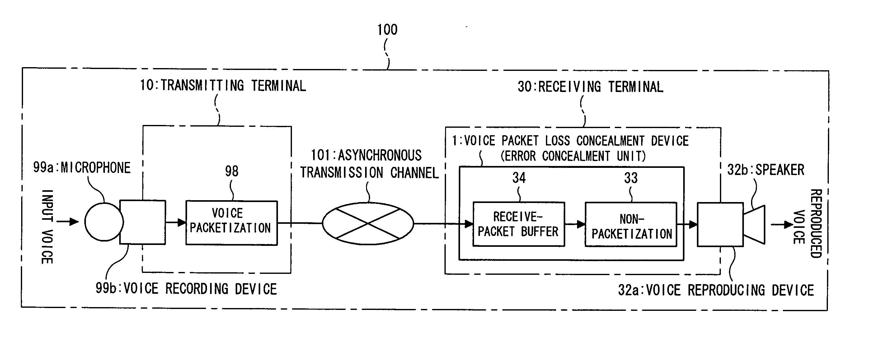
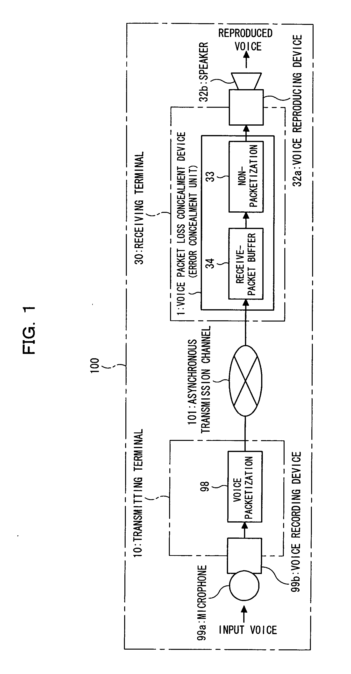
[0067]FIG. 1 is a block diagram of a VoIP communication system to which the present invention is applied. The VoIP communication system 100 shown in FIG. 1 is a voice packet communication system in which voice data (encoded voice data) is packetized and transmitted, comprising an asynchronous transmission channel 101, a transmitting terminal 10, and a receiving terminal 30. A voice packet loss concealment device of the present invention is applied to a voice reproduction processing section of the receiving terminal 30 to be described hereinafter.

[0068] (1) Configuration of the VoIP Communication System 100

[0069] (1-1) Asynchronous Transmission Channel 101

[0070] The asynchronous transmission channel 101 is an IP network (e.g. Internet) in which voice packets are transferred.

[0071] The asynchronous transmission channel 101 is a best effort type network including transmission delay fluctuation. Although the asynchronous transmission channel 101...

second embodiment

(B) Description of the Present Invention

[0174]FIG. 8 is a block diagram of a voice packet loss concealment device according to a second embodiment of the present invention. A pitch signal generating section 33e of the voice packet loss concealment device 1b shown in FIG. 8 is adapted to output a pitch signal by multiplying a predetermined weighting coefficient to each of the pre-loss and post-loss power fluctuation characteristics, and adding the weighted pre-loss and post-loss power fluctuation characteristics to each other.

[0175] It is noted that elements shown in FIG. 8 having the same numerals as in the first embodiment are the same as mentioned above, and that redundant descriptions will be omitted to explain mainly the operation of the pitch signal generating section 33e.

[0176] The pitch signal generating section 33e generates a pitch signal “pitsig0” corresponding to the pitch fluctuation characteristics “dlag” based on a pre-loss voice signal “outbuf”, as indicated by Form...

third embodiment

(c) Description of the Present Invention

[0186]FIG. 9 is a block diagram of a voice packet loss concealment device according to a third embodiment of the present invention. The voice packet loss concealment device 1c shown in FIG. 9 has a monitor function for monitoring the number of voice packets accumulated in a receive-packet buffer 34, and a function for changing the operation pattern (operation mode) of a pitch fluctuation estimating section 33d, a power fluctuation estimating section 33c, and a pitch signal generating section 33e in accordance with the number of voice packets acquired by the monitor function. Functions other than above are the same as that of the voice packet loss concealment device 1b of the second embodiment. Also, elements shown in FIG. 9 having the same numerals as above are the same as mentioned above. Descriptions about the same elements as in the second embodiment will hereinafter be omitted to describe the operation of different elements.

[0187] An accu...


PUM


Abstract

In a voice packet communication system, a voice packet loss concealment device compensates for the deterioration of voice quality due to voice packet loss. In the device, a detecting section detects a loss of a voice packet and outputting information; an estimating section estimates the voice characteristics of the lost segment using a pre-loss voice packet received before the lost segment or a post-loss voice packet received after the lost segment; a pitch signal generating section generates a pitch signal having the voice characteristics; and a lost packet generating section outputs the pitch signal generated by the pitch signal generating section, with the voice characteristics estimated by the estimating section, which allows abnormal noise and feeling of mute, subjective deterioration of naturalness and continuity to be improved, and the voice packet loss concealment to be further improved.

Description

TECHNICAL FIELD [0001] The present invention relates to a voice packet loss concealment device, a voice packet loss concealment method, a receiving terminal, and a voice communication system, which are suitable for use in compensating for the deterioration of voice quality caused by voice packet loss in, for example, a receiving terminal in a voice packet communication system in which voice data is packetized and transmitted. BACKGROUND ART [0002] In general, it is often the case that transmission rate is used as a criterion for evaluating the quality of access networks. Classifying networks based on transmission band knows band assurance type and best effort type ones. In a band assurance type network, a network operator always assures users of a constant transmission band regardless of the number of users, while in a best effort type network not always assure users of a constant transmission band. [0003] In recent years due to the explosive growth of the Internet, VoIP (Voice over...

Claims


Application Information

Patent Timeline
IPC IPC(8): G01L19/00G10L19/005G10L25/21G10L25/90H04L12/56H04L29/06H04M7/00
CPCG10L19/005H04L29/06027H04L65/80H04L65/607H04M7/006H04L65/70H04L65/1101
Inventor TSUCHINAGA, YOSHITERUOTA, YASUJISUZUKI, MASANAOTANAKA, MASAKIYOSHIRAKAWA, MIYUKI
Owner FUJITSU LTD
Why Eureka
Try Eureka