
Device for rotating with a multisided socket

Inactive Publication Date: 2005-08-04
MARINE CANADA ACQUISITIONS INC
View PDF11 Cites 1 Cited by
  • Summary
  • Abstract
  • Description
  • Claims
  • Application Information

AI Technical Summary

Benefits of technology

"The invention provides a device for rotating with a first rotatable member and a second member that tightly engages with the first member. This device can be easily adjusted to a total of m.n rotational positions, reducing production costs. The invention also provides a way to mount a device, such as a potentiometer, at different rotational positions by using a coupling with a third multisided member and a complementary shaped opening. This arrangement is simpler and less expensive to construct than more elaborate adjustment mechanisms. Additionally, the invention offers a quick and reliable way of connecting two conductors together by placing them in a socket and then pressing a post with a plurality of rows of circumferential projections into the socket, resulting in multiple point crimps between the post and the conductors which ensures adequate electrical conductivity."

Problems solved by technology

In addition it is sometimes necessary to measure very accurately the angle of rotation of such a component.

Method used


Image

  • Device for rotating with a multisided socket
  • Device for rotating with a multisided socket
  • Device for rotating with a multisided socket

Examples


Embodiment Construction

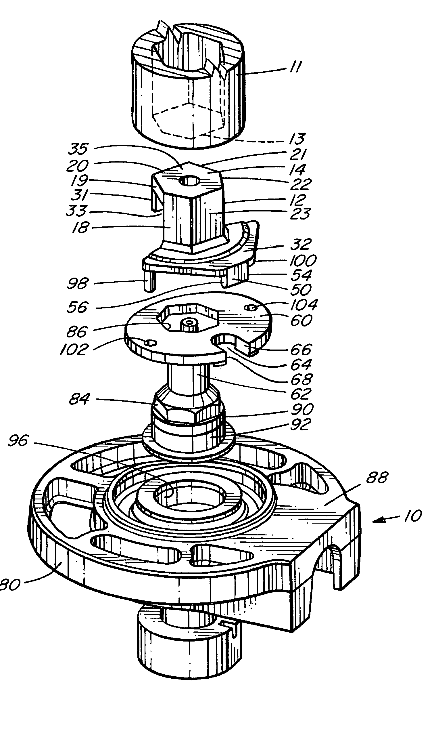
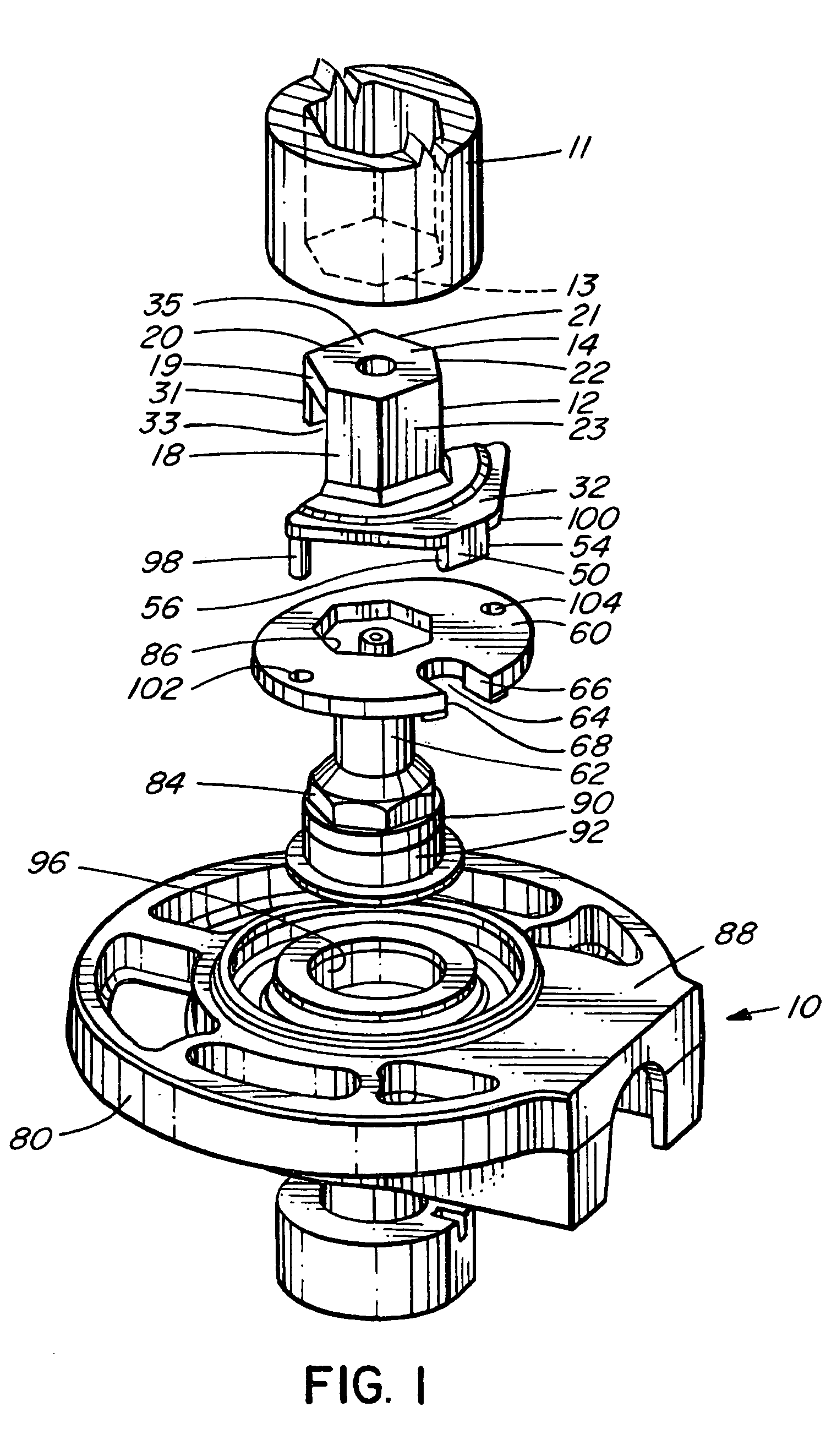
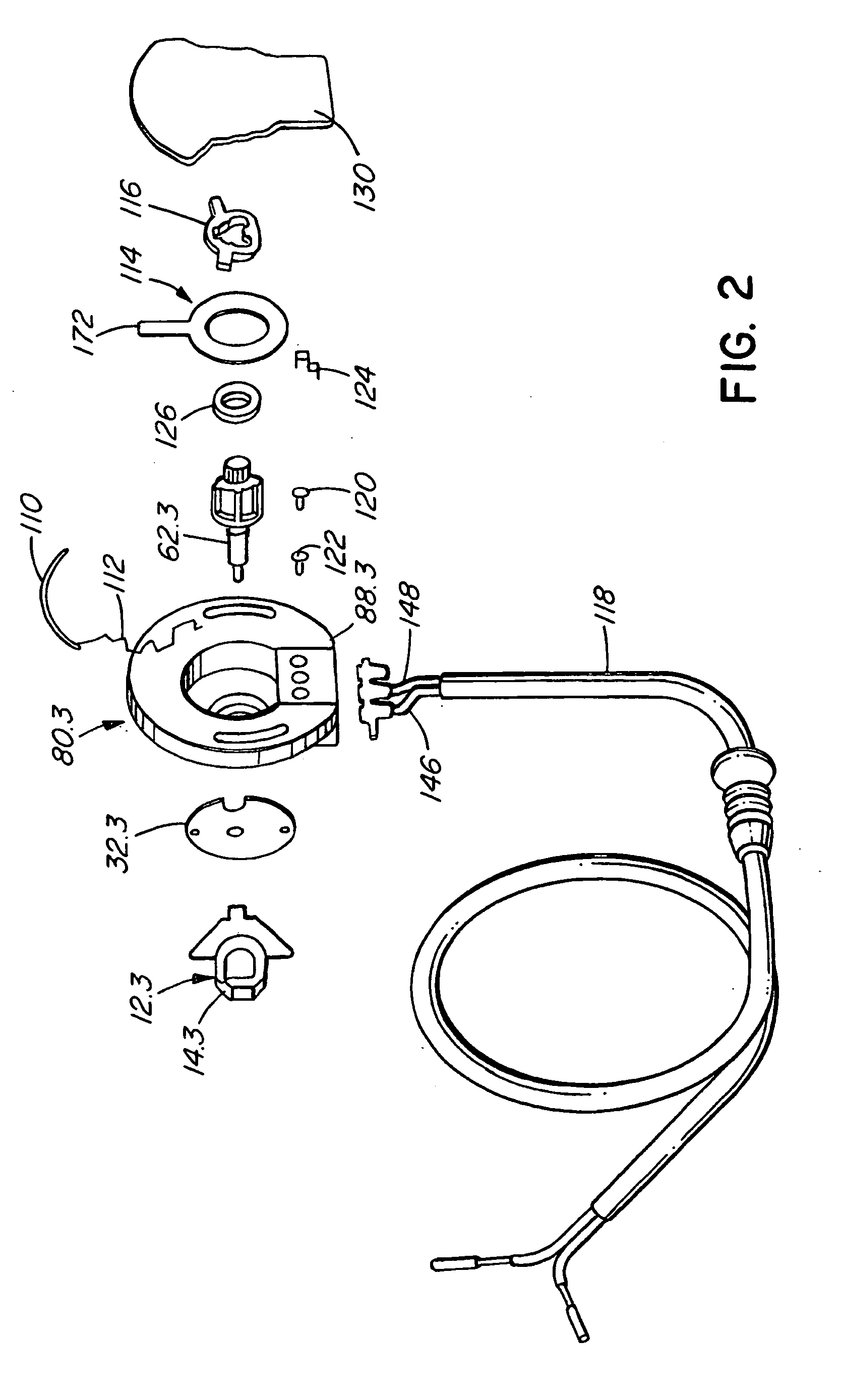
[0029] Referred to the drawings, and first FIGS. 10 and 11, these show a marine stern drive unit 300 which, in this example, includes an inboard / outboard motor 302 located within a boat 304 having a transom 306. A stern drive 308 is mounted on the transom and is pivotal between the lower position shown in solid lines and the raised position shown in stippled lines. There is a steering cylinder 310 used to steer the stern drive. The stern drive is raised and lowered by trim cylinders 312, only one of which is shown, there being a similar trim cylinder on the opposite side. The rear ends of the trim cylinders are mounted on the drive at 313 and the front ends 314 are mounted on a gimbal ring 316. The drive pivots up and down on two pins (not shown) which go through the gimbal ring. A trim sender 10 is mounted on the gimbal ring and has a nut, described below, which fits onto the pivot pin. The trim sender has a case, described below, which is mounted rigidly onto the gimbal ring, whil...


PUM


Abstract

A device for rotating with a rotatable first member includes a second member having a portion engageable with the first member. The portion has a first part and a second part which is resiliently biased away from the first part. The second member tightly engages the first member. There may be a device for measuring rotation of the shaft such as a potentiometer. The rotation measuring device may include an electrical connector for the potentiometer including a socket and a post which is pressable into the socket. The device may also include a rotationally adjustable connector. There may be a coupling connected to the second member which includes a third member with a portion having n sides and a fourth member with a portion having n sides which receives the portion of the third member in a mating relationship, thereby allowing the device to be adjusted to a total of at least m.n rotational positions. The second member preferably has a projection which slidably engages a slot in the third member allowing for non-coaxial rotation, and minimal backlash, of the device for measuring rotation relative to the first member.

Description

BACKGROUND OF THE INVENTION [0001] This invention relates to a device for rotating with a rotatable member and, in particular, to a device which is capable of measuring trim angle for a marine craft. [0002] There are many cases where screws, bolts, or other components having multisided sockets are rotated, sometimes accompanied by rotation of a member about an axis which is non-co-axial with the sockets. In addition it is sometimes necessary to measure very accurately the angle of rotation of such a component. [0003] For example, such a component, often rotated by a hexagonal socket or a hexagonal drive nut, is used in marine drive systems. The angle of rotation of the component indicates the amount of trim. [0004] It is an object of the invention to provide an improved device for rotating with a multi-sided member and which is capable of rotating with such a member without any significant backlash between the device and the member. [0005] It is also an object of the invention to pr...

Claims


Application Information

Patent Timeline
Patent Type & Authority Applications(United States)
IPC IPC(8): B63H20/10
CPCB63H20/10
Inventor SCOTT, JON DAVID EDWARDFLOOD, STEPHEN RAYMOND
Owner MARINE CANADA ACQUISITIONS INC
Learn More