Modular motor assembly structure

a technology of modular motors and motor assemblies, applied in the direction of dynamo-electric machines, shafts and bearings, dynamo-electric components, etc., can solve the problems of difficulty for general users to complete the connection, and the failure of conventional motor assemblies to achieve the purpose of modularization, so as to simplify assembly procedures and reduce assembly length

Active Publication Date: 2020-07-16
DELTA ELECTRONICS INC
View PDF0 Cites 2 Cited by
  • Summary
  • Abstract
  • Description
  • Claims
  • Application Information

AI Technical Summary

Benefits of technology

[0005]An object of the present invention is to provide a modular motor assembly structure. The main body of the modular motor assembly structure is slightly mutated. By modularizing the mounting shaft hole with standard interface size in the motor assembly structure, a wide range of users can directly connect the motor assembly structure with the application device or the corresponding equipment. It benefits to meet the requirements of the market and be adjustable according to the existing market. Moreover, the common mounting components, such as the couplings, the motor flanges and so on, are omitted. Thus, the purposes of reducing assembly length and simplifying assembly procedures are achieved.
[0006]Another object of the present invention is to provide a modular motor assembly structure. With the geometric profile of the specially designed combination keys, the functions of eliminating the problem of mounting tolerances, facilitating the installation and transmitting the rigidity of rotating power can be achieved. The assembly structure and the assembly method are simplified. The function of the transmitting the rigidity between the modular motor assembly structure and the client application device is achieved. In addition, the special structural design of the combination key can provide the functions of elastic cushioning and adjusting tolerances by disposing the groove and the surface inclined at an angle, which can effectively improve the convenience of assembly, and ensure the functions of rigid connection and elastic cushioning to eliminate the problem of tolerances. Consequently, zero backlash is achieved. It is beneficial to achieve the effects of high precision and rapid response. Thus, the modular motor assembly structure of the present disclosure is more suitable for various rotating components, such as driving screws, pulleys, gears, reducers and so on, in the application device.

Problems solved by technology

It is difficult for general users to complete the connection of the straight-through module, which makes the conventional motor assembly fail to achieve the purposes of modularization.

Method used


Image

  • Modular motor assembly structure
  • Modular motor assembly structure
  • Modular motor assembly structure

Examples


Embodiment Construction

[0027]The present invention will now be described more specifically with reference to the following embodiments. It is to be noted that the following descriptions of preferred embodiments of this invention are presented herein for purpose of illustration and description only. It is not intended to be exhaustive or to be limited to the precise form disclosed.

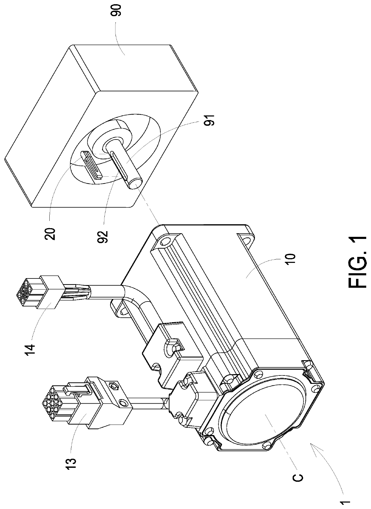
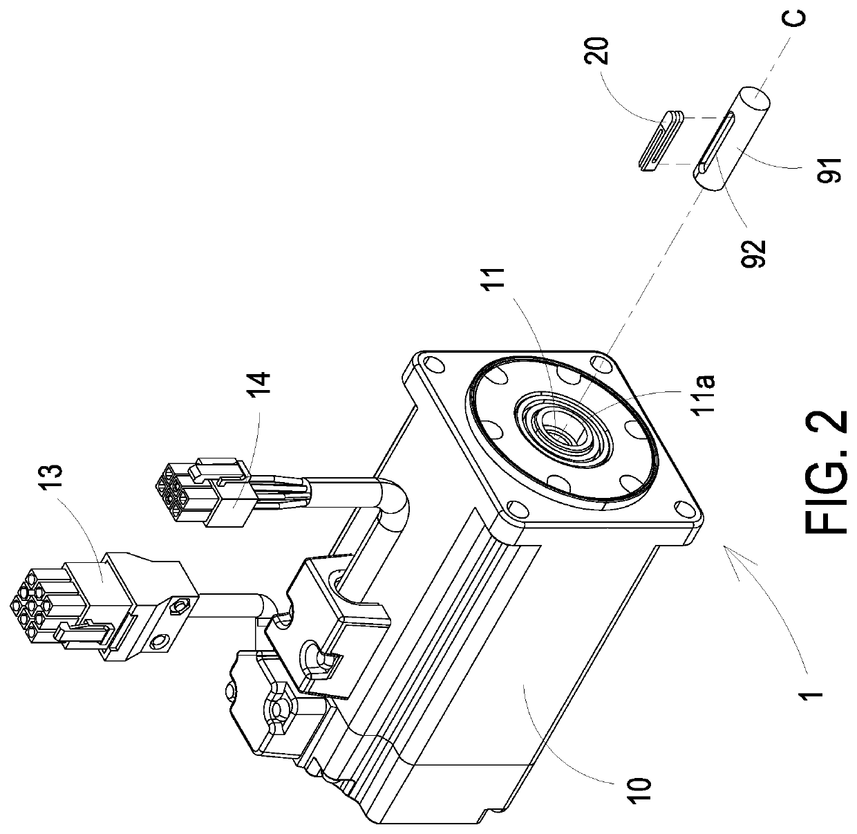
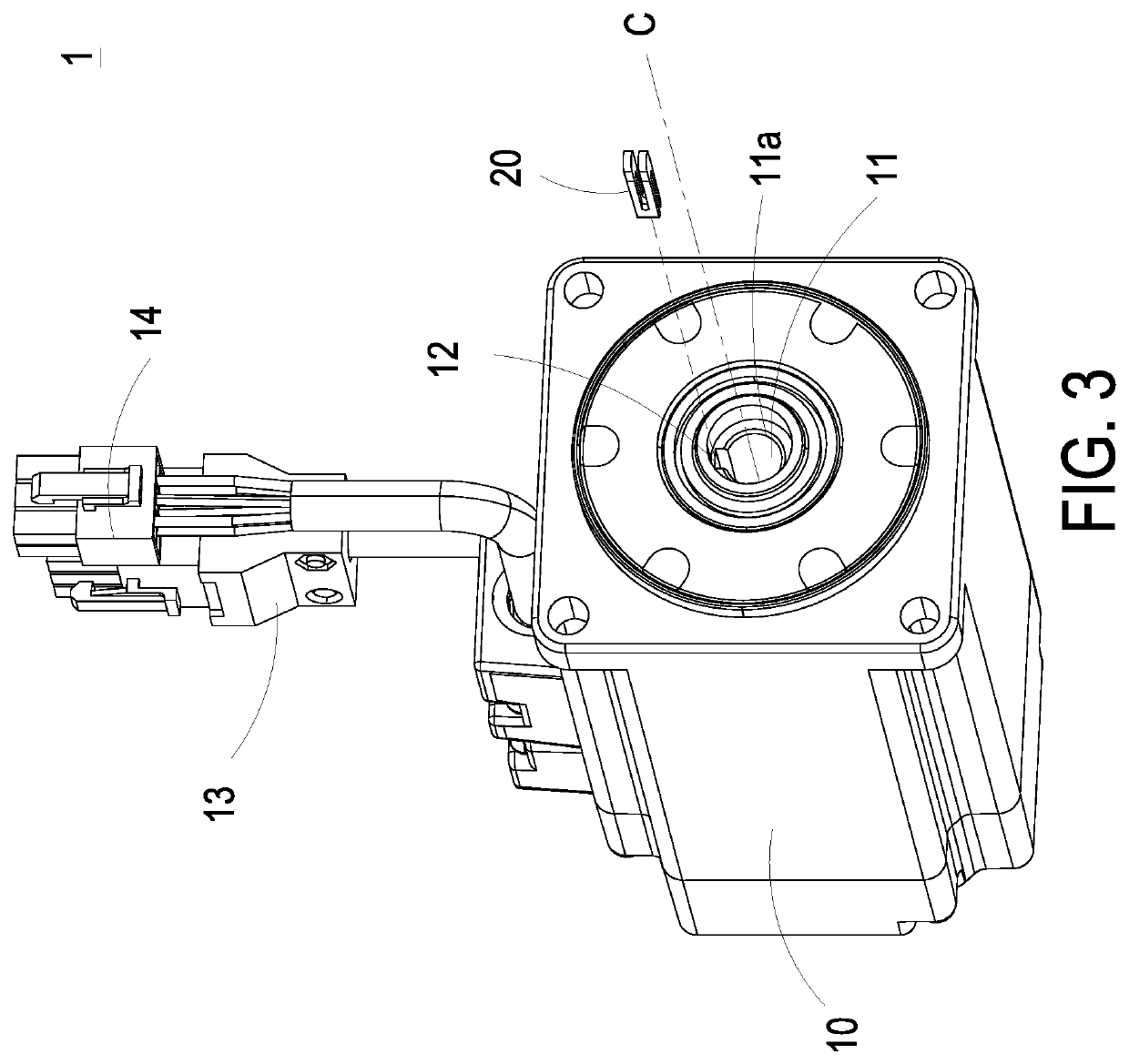
[0028]FIGS. 1 and 2 are perspective structural views illustrating a modular motor assembly structure and a corresponding application device according to a first preferred embodiment of the present invention. FIG. 3 shows relationship of the main body and the combination key of the modular motor assembly structure according to the first preferred embodiment of the present invention. FIG. 4 is a front view illustrating the main body of the modular motor assembly structure according to the first preferred embodiment of the present invention. FIGS. 5 and 6 are perspective structural views illustrating the combination key of the modul...


PUM


Abstract

A modular motor assembly structure is disclosed and configured to couple with a drive shaft of an application device. The drive shaft includes a receiving slot. The modular motor assembly includes a main body and a combination key. The main body includes a shaft hole and a key groove. The shaft hole includes an opening and a central axis. The key groove is disposed on a side wall around the shaft hole and parallel to a central axis of the shaft hole. The combination key has a front end and a rear end. When one end of the drive shaft is inserted into the shaft hole along the central axis of the shaft hole, the combination key is at least partially accommodated in the receiving slot, and the front end faces the key groove. The combination key has a continuously increasing thickness from the front end to the rear end.

Description

CROSS-REFERENCE TO RELATED APPLICATION[0001]This application claims the benefit of U.S. Provisional Application No. 62 / 791,624 filed on Jan. 11, 2019, and entitled “MODULAR MOTOR ASSEMBLY STRUCTURE”, the entirety of which is hereby incorporated by reference.FIELD OF THE INVENTION[0002]The present invention relates to a motor assembly structure, and more particularly to a modular motor assembly structure.BACKGROUND OF THE INVENTION[0003]In a conventional motor assembly structure for an application device, a straight-through module is generally used to connect with the client application device. The main purpose of utilizing the straight-through module is to shorten the overall length and reduce the cost of the coupling components between the motor assembly structure and the application device. Furthermore, the straight-through module facilitates to increase the rigidity transmission and the response speed of the motor, and it benefits to increase the accuracy of use. Generally, in th...

Claims


Application Information

Patent Timeline
Patent Type & Authority Applications(United States)
IPC IPC(8): F16D1/08H02K7/00F16D1/12
CPCH02K7/003F16D1/0894F16D1/12F16C3/02F16D1/04F16D1/0876
Inventor HUANG, ZI-XUAN
Owner DELTA ELECTRONICS INC
Why Eureka
Try Eureka