Bond testing machine and cartridge for a bond testing machine comprising a plurality of test tools

a technology of bond testing machine and test tool, which is applied in the direction of instruments, material analysis, and using mechanical means, can solve the problems of difficult contact with the substrate surface, inconvenient use, and inability to accurately detect the surface, so as to improve the geneva drive mechanism, reduce the vibration of the test tool, and eliminate the possibility of rotational positioning errors

Inactive Publication Date: 2016-11-01
NORDSON CORP
View PDF5 Cites 1 Cited by
  • Summary
  • Abstract
  • Description
  • Claims
  • Application Information

AI Technical Summary

Benefits of technology

[0020]Providing a plurality of test tool assemblies that can be selectively moved to a use position within a single cartridge allows an operator to change tools without having to demount and remount different test tool cartridges every time a different test tool is required. This improves the ease of operation and saves the operator time. The test tool assemblies are rotated by the rotary mechanism so that each test tool can be moved to and from a use position. The test tool assemblies may be fixed relative to one another so that all of the test tool assemblies rotate simultaneously, with, at most, only a single test tool assembly being in a use position at any one time.
[0049]Advantageously, the driven wheel comprises at least two resilient elements in frictional engagement with the drive wheel. Each resilient element may comprise a compliant beam extending from the driven wheel, the complaint beam configured at its free end to be urged into contact with a surface of the drive wheel. The force applied by the resilient arm on the drive wheel may be directed against a bearing surface on the drive wheel and advantageously in a radial direction with respect to the drive wheel. In this manner, it is possible to load the driven wheel against the drive wheel to obtain zero backlash in each position, meaning that driven wheel can be locked in the desired position with respect to the drive wheel when the drive wheel is stopped.

Problems solved by technology

Several difficulties arise.
Friction and stiction in the mechanism of the device itself may cause difficulties in sensing contact with the substrate surface.
Imprecise surface sensing will inevitably affect the distance by which the test tool is withdrawn, and thus the height at which the bond is sheared.
Such movement may seriously affect the accuracy of the test results and significant movement of the test tool at the test height may damage an adjacent bond or wire.
The twin objectives of both a low contact force when sensing the surface of the substrate and accurate control of the test height are difficult to resolve.

Method used


Image

  • Bond testing machine and cartridge for a bond testing machine comprising a plurality of test tools
  • Bond testing machine and cartridge for a bond testing machine comprising a plurality of test tools
  • Bond testing machine and cartridge for a bond testing machine comprising a plurality of test tools

Examples


Embodiment Construction

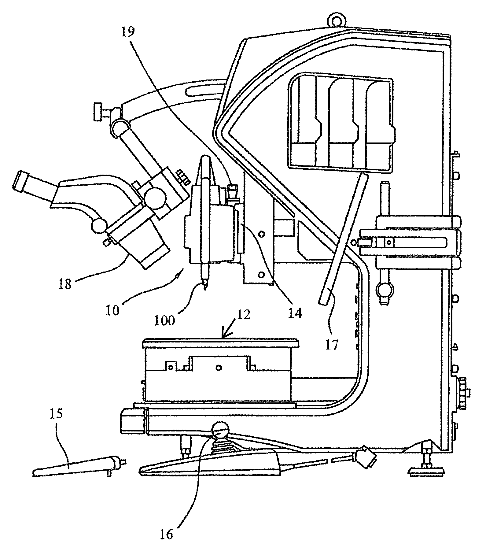
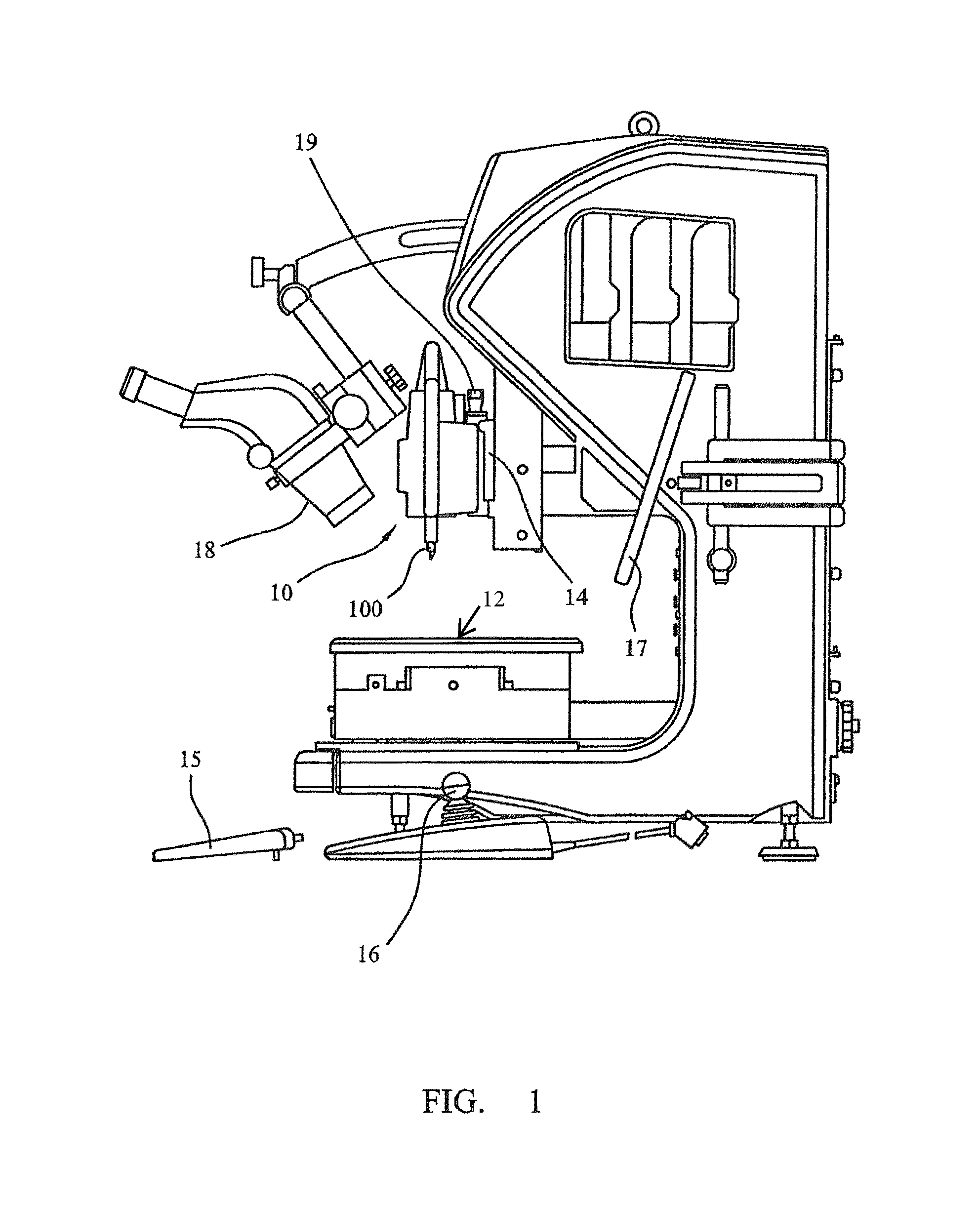
[0086]FIG. 1 is an illustration of a bond testing machine in accordance with the present invention. The machine comprises a cartridge 10 containing a plurality of test tool assemblies 100 (only one of which is visible in FIG. 1), which is mounted to the moving assembly 14 of the device. Beneath the test tool assemblies 100 is a motorised stage table 12, on which samples to be tested can be mounted. The samples are typically substrates upon which solder ball deposits and wire bonds are formed to connect electronic components on the substrate.

[0087]The cartridge 10 is moveable in a direction normal to the sample, hereafter referred to as the Z-direction or axial direction, by the moving assembly 14. This allows the test tool assemblies to be positioned relative to the sample and provides the movement necessary for a pull test or to position the tool for a shear test. The moving assembly 14 that supports cartridge 10 is mounted to a ball screw, or lead screw and nut (not shown), and ca...


PUM

PropertyMeasurementUnit
rotationaaaaaaaaaa
flexibleaaaaaaaaaa
strengthaaaaaaaaaa

Abstract

A cartridge suitable for use in a bond testing machine includes a plurality of a different test tools. A rotary mechanism is provided and each of the plurality of different test tools is mounted to the rotary mechanism angularly spaced from one another. A drive unit is coupled to the rotary mechanism and is configured to rotate the rotary mechanism to move each of the plurality of different test tools to and from a use position. An air interface receives compressed air from a corresponding air interface on a positioning assembly of the bond testing machine.

Description

FIELD OF THE INVENTION[0001]The present invention relates to a device for testing the strength of electrical bonds on semiconductor devices. In particular, the invention relates to a device that is able to perform different types of tests such as a shear test, a pull test and a push test on electrical bonds.BACKGROUND TO THE INVENTION[0002]Semiconductor devices are very small, typically from 5 mm×5 mm square to 50 mm×50 mm square, and typically comprise numerous sites for the bonding of electrical conductors to a semiconductor substrate. Each bond consists of a solder ball / bump or copper pillar or wire.[0003]It is necessary to test the bond strength of the bonds, in order to be confident that a particular bonding method is adequate. Because of the very small size of the bonds, tools used to test the bond strength of these bonds must be able to measure very small forces and deflections accurately.[0004]There are several different types of bond tests that are used to test bond strengt...

Claims


Application Information

Patent Timeline
Patent Type & Authority Patents(United States)
IPC IPC(8): G01N3/24G01N19/04G01N3/04G01N3/00
CPCG01N3/24G01N3/00G01N3/04G01N19/04G01N2203/0003G01N2203/0017G01N2203/0025G01N2203/0067G01N2203/0296H01L2224/859
Inventor DEARDS, ROBERT BRIANMAYES, IAN CHRISTOPHERBUGG, MARTINLILLEY, DAVID T.
Owner NORDSON CORP
Why Eureka
Try Eureka