Heat sink including redundant fan sinks

a technology of fan sinks and heat sinks, applied in the field of heat sinks, can solve the problems of increasing failure mechanisms such as electromigration, increasing circuits, and increasing heat generation of modern electronic devices, and increasing the cooling capacity of the remaining fan sinks. , to achieve the effect of increasing the cooling efficiency of the remaining fan sinks

Inactive Publication Date: 2005-08-04
HEWLETT PACKARD DEV CO LP
View PDF12 Cites 38 Cited by
  • Summary
  • Abstract
  • Description
  • Claims
  • Application Information

AI Technical Summary

Benefits of technology

[0005] A cooling device for electronic devices is built comprising at least two fan sinks thermally coupled together such that when one fan sink fails, the remaining fan sinks are able to compensate for the failed fan sink. Optionally, the remaining fan sinks may be controlled to speed up upon detection of a failure, increasing their cooling capacity to compensate for the failed fan sink. Also optionally, a thermal coupling device such as heat pipes may be used as part of the thermal coupling between the fan sinks to increase the cooling efficiency of the remaining fan sinks to the device or devices closest to the failed fan sink. Also optionally, the thermal coupling device may be configured to allow some flexibility in the cooling device assembly allowing for the cooling of non-coplanar electronic devices.

Problems solved by technology

Modern electronic devices, such as microprocessors, not only generate large amounts of heat during operation, but are also temperature sensitive.
Most integrated circuits run at slower speeds as temperature increases, and also failure mechanisms such as electromigration increase as temperature increases.
However one problem inherent with fan sinks is that since they typically are only used where their cooling capacity is necessary, if the fan fails, the electronic device will overheat, sometimes catastrophically.

Method used


Image

  • Heat sink including redundant fan sinks
  • Heat sink including redundant fan sinks
  • Heat sink including redundant fan sinks

Examples


Embodiment Construction

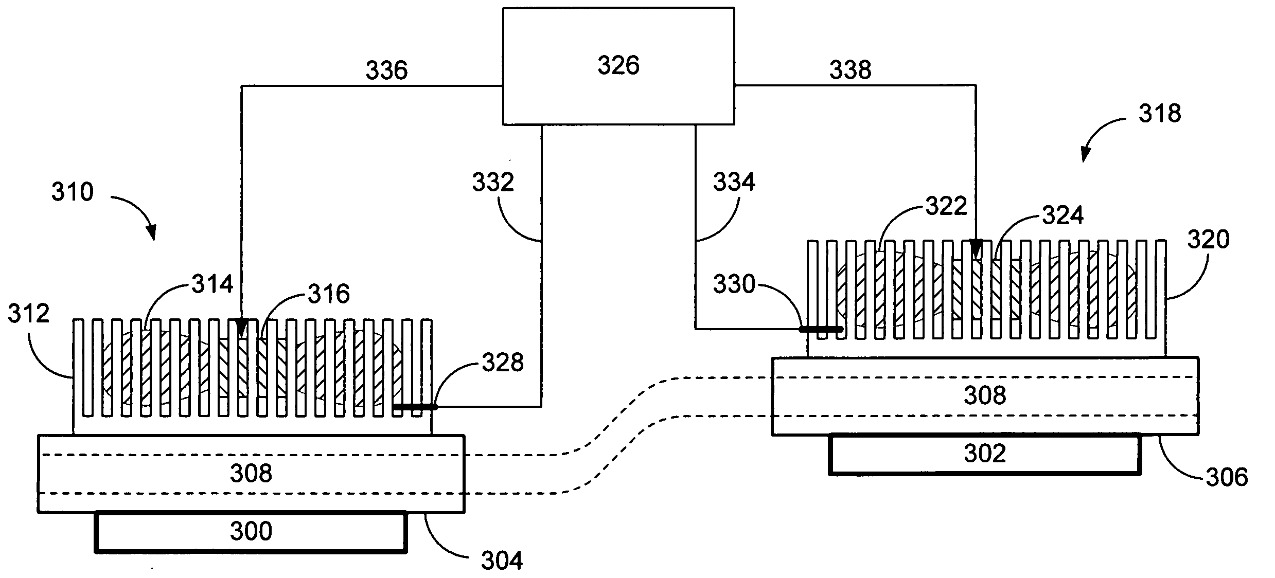
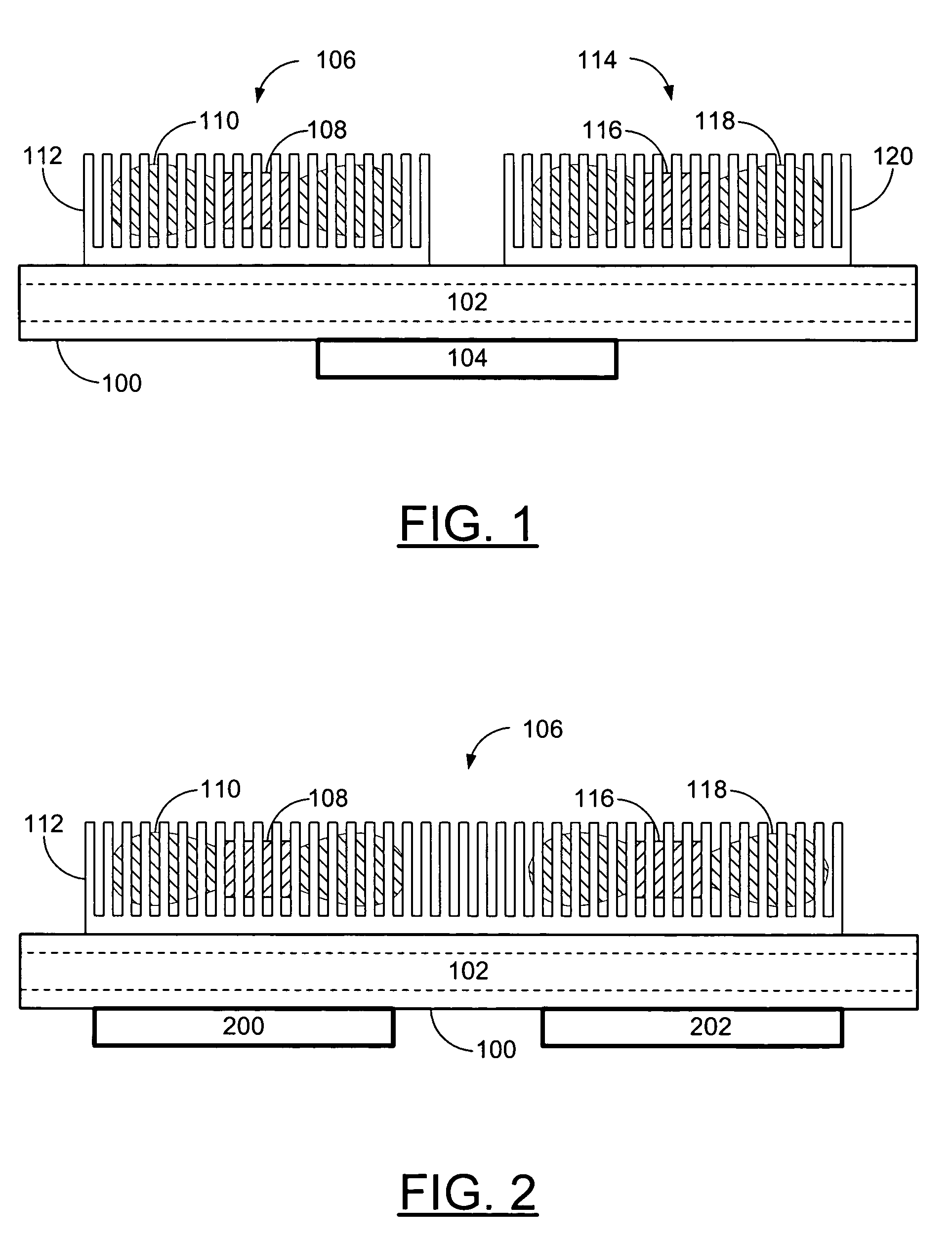
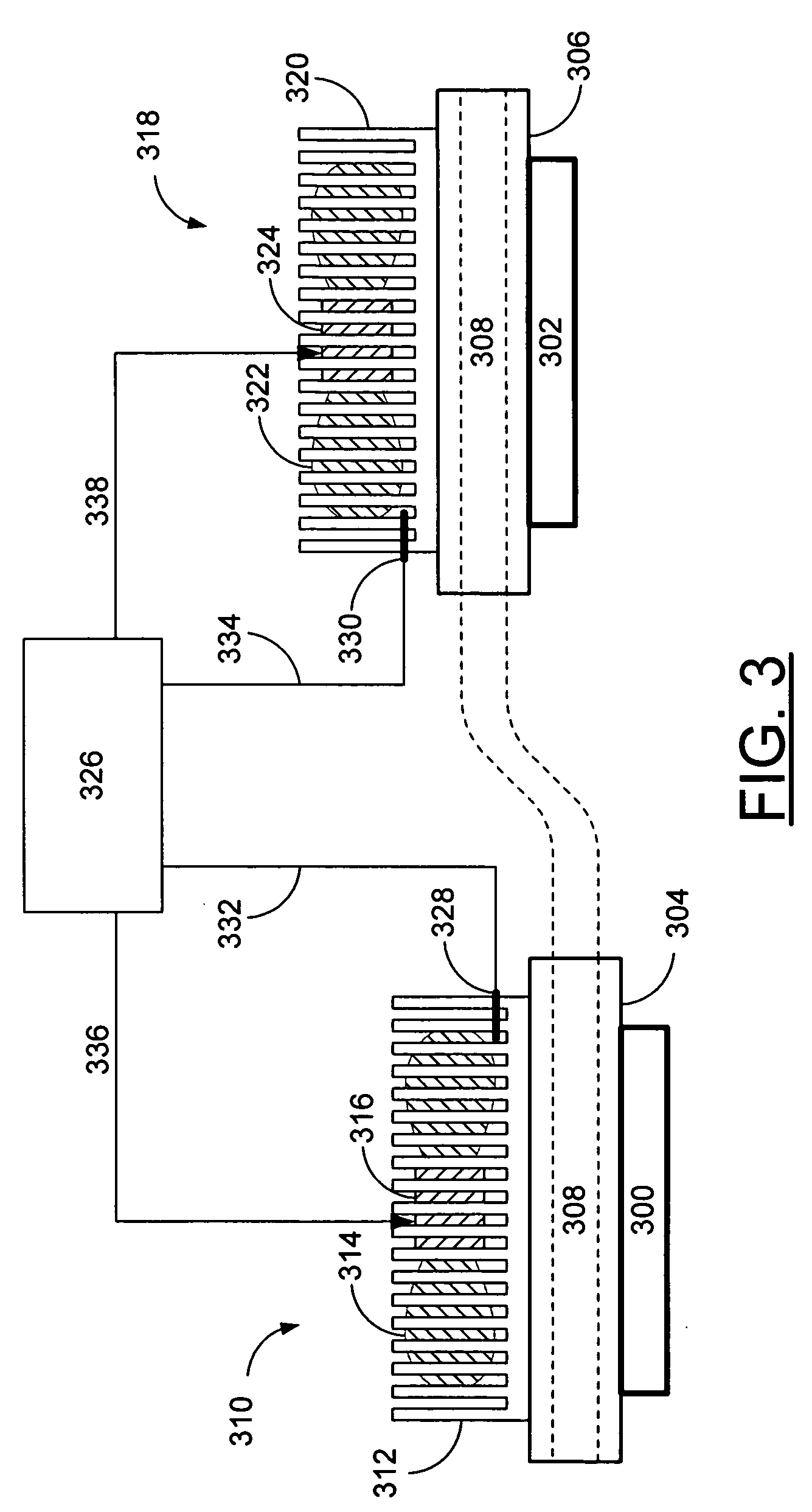
[0010]FIG. 1 is a front view of a redundant fan sink design including heat pipes according to the present invention configured to cool a single electronic device. In this example embodiment of the present invention a heat sink is built including two fan sinks. Other embodiments of the present invention may include any number of additional fan sinks to the two shown in FIG. 1. An electronic device 104 that generates heat is thermally and mechanically coupled to a heat spreader 100. In this example embodiment of the present invention, the heat spreader 100 includes at least one heat pipe 102 to increase the efficiency of the heat spreader 100 in eliminating hot spots over the electronic device 104. Other embodiments of the present invention may not require the use of heat pipes. A first fan sink 106 comprising a first heat sink 112 surrounding a first fan is thermally and mechanically coupled to the heat spreader 100. The first fan includes a first motor 108 and first fan blades 110. ...


PUM


Abstract

A cooling device for electronic devices is built comprising at least two fan sinks thermally coupled together such that when one fan sink fails, the remaining fan sinks are able to compensate for the failed fan sink. Optionally, the remaining fan sinks may be controlled to speed up upon detection of a failure, increasing their cooling capacity to compensate for the failed fan sink. Also optionally, a thermal coupling device such as heat pipes may be used as part of the thermal coupling between the fan sinks to increase the cooling efficiency of the remaining fan sinks to the device or devices closest to the failed fan sink. Also optionally, the thermal coupling device may be configured to allow some flexibility in the cooling device assembly allowing for the cooling of non-coplanar electronic devices.

Description

FIELD OF THE INVENTION [0001] The present invention relates generally to the field of heat sinks and more specifically to the field of fan sink designs with redundancy. BACKGROUND OF THE INVENTION [0002] Modern electronic devices, such as microprocessors, not only generate large amounts of heat during operation, but are also temperature sensitive. Most integrated circuits run at slower speeds as temperature increases, and also failure mechanisms such as electromigration increase as temperature increases. Thus, the art of cooling electronic devices to a temperature within their operating range is critical to the proper operation of computers and other large electronic devices. [0003] One common configuration used for cooling electronic devices is the fan sink. A fan sink is created by constructing a heat sink substantially surrounding a fan, configured such that when the fan is operating it creates substantial airflow over the heat sink. Often the fan sink is attached to an electroni...

Claims


Application Information

Patent Timeline
Patent Type & Authority Applications(United States)
IPC IPC(8): H01L23/34H01L23/427H01L23/467H05K7/20
CPCH01L23/34H01L23/427H01L23/467H01L2924/0002H01L2924/00
Inventor BELADY, CHRISTIAN L.SIMON, GLENN C.MALONE, CHRISTOPHER G.HARRIS, SHAUN L.
Owner HEWLETT PACKARD DEV CO LP
Why Eureka
Try Eureka