Anti-tracking earth boring bit with selected varied pitch for overbreak optimization and vibration reduction

a technology of over-break optimization and anti-tracking, applied in the field of drill bits, can solve the problems of remaining to be solved, loss of drilling efficiency, and increased wear of the bi

Inactive Publication Date: 2005-08-04
AARON ANNA VICTORVNA +1
View PDF22 Cites 37 Cited by
  • Summary
  • Abstract
  • Description
  • Claims
  • Application Information

AI Technical Summary

Benefits of technology

[0019] 3. Substantial reduction of detrimental axial resonance frequency vibration of drill bit or tool which are restr

Problems solved by technology

One problem that remains to be solved is that of “tracking.” Tracking occurs when a cutting element (tungsten-carbide insert or steel tooth) falls in the same impression that was made previously by the same or another cutting element.
This results in loss of drilling efficiency since the primary mode of contact between cutters and formation is between the surface of the cutter and formation rather than between the cutting elements and formation.
This results in increased wear of the bit as well as reduction in feet per hour or penetration rate.
Conventional solutions to tracking include increasing the weight-on-bit (WOB), but, as can be expected, this reduces bit life because of the additional strain on bit components.
The disadvantage of such solutions is that overbreak effect is not utilized, specific energy increases and the cost of the drill bit is augmented.
The drawback of this approach is that the cutting elements that are sliding and scraping will wear faster while tracking will not be completely eliminated.
Any deviation from equal pitch, can dramatically increase bit vibration, again causing premature bit wear.
This app

Method used


Image

  • Anti-tracking earth boring bit with selected varied pitch for overbreak optimization and vibration reduction
  • Anti-tracking earth boring bit with selected varied pitch for overbreak optimization and vibration reduction
  • Anti-tracking earth boring bit with selected varied pitch for overbreak optimization and vibration reduction

Examples


Embodiment Construction

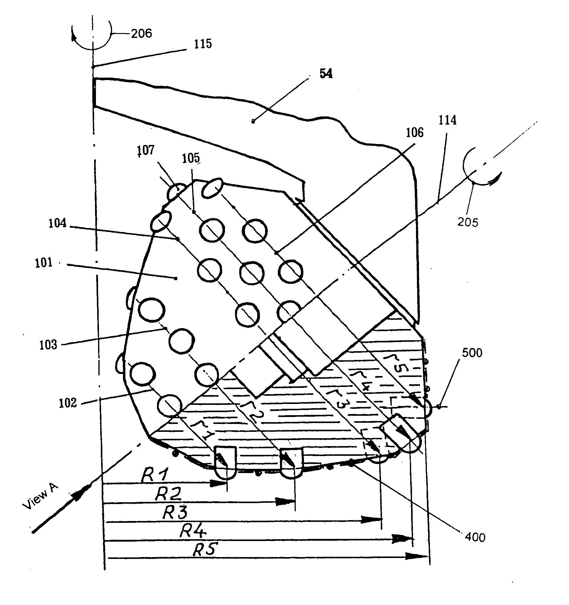
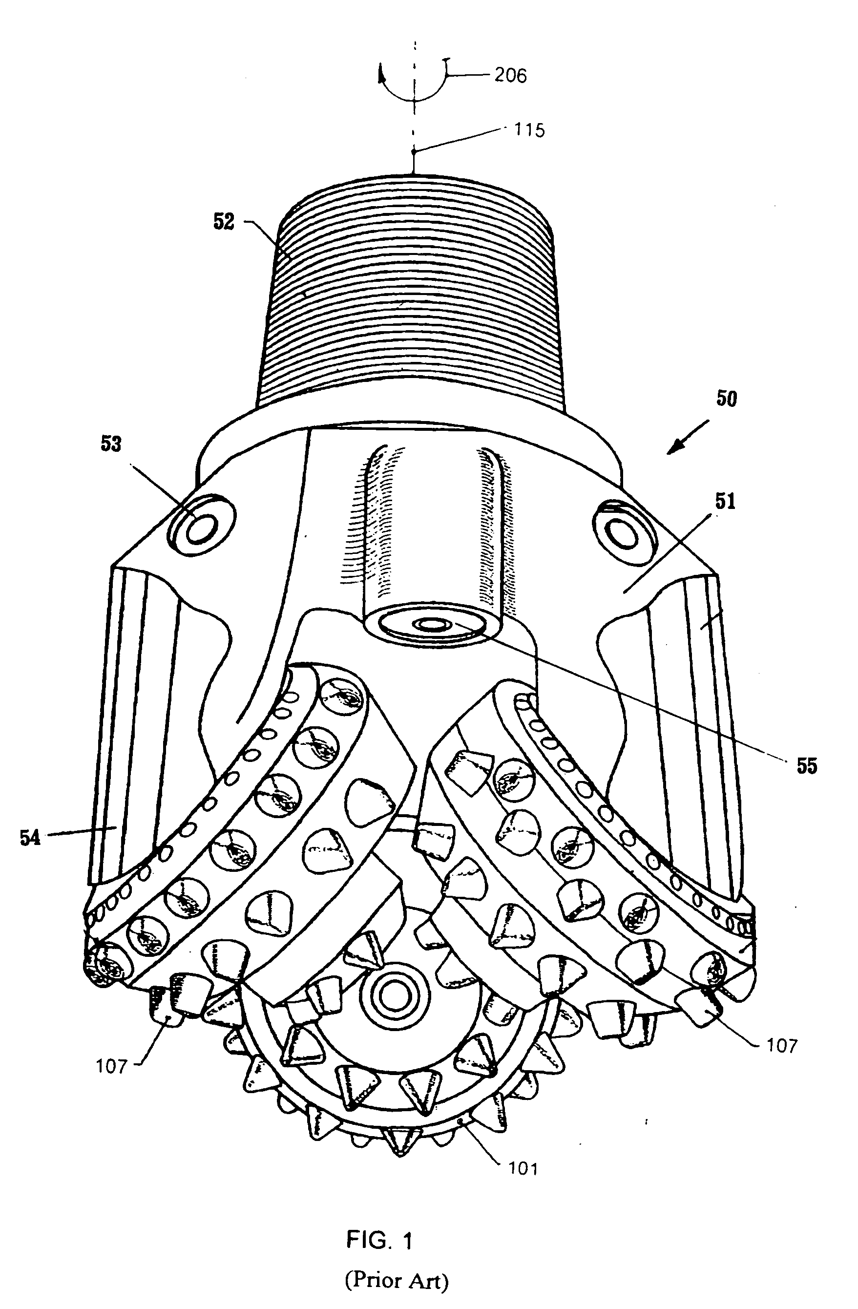
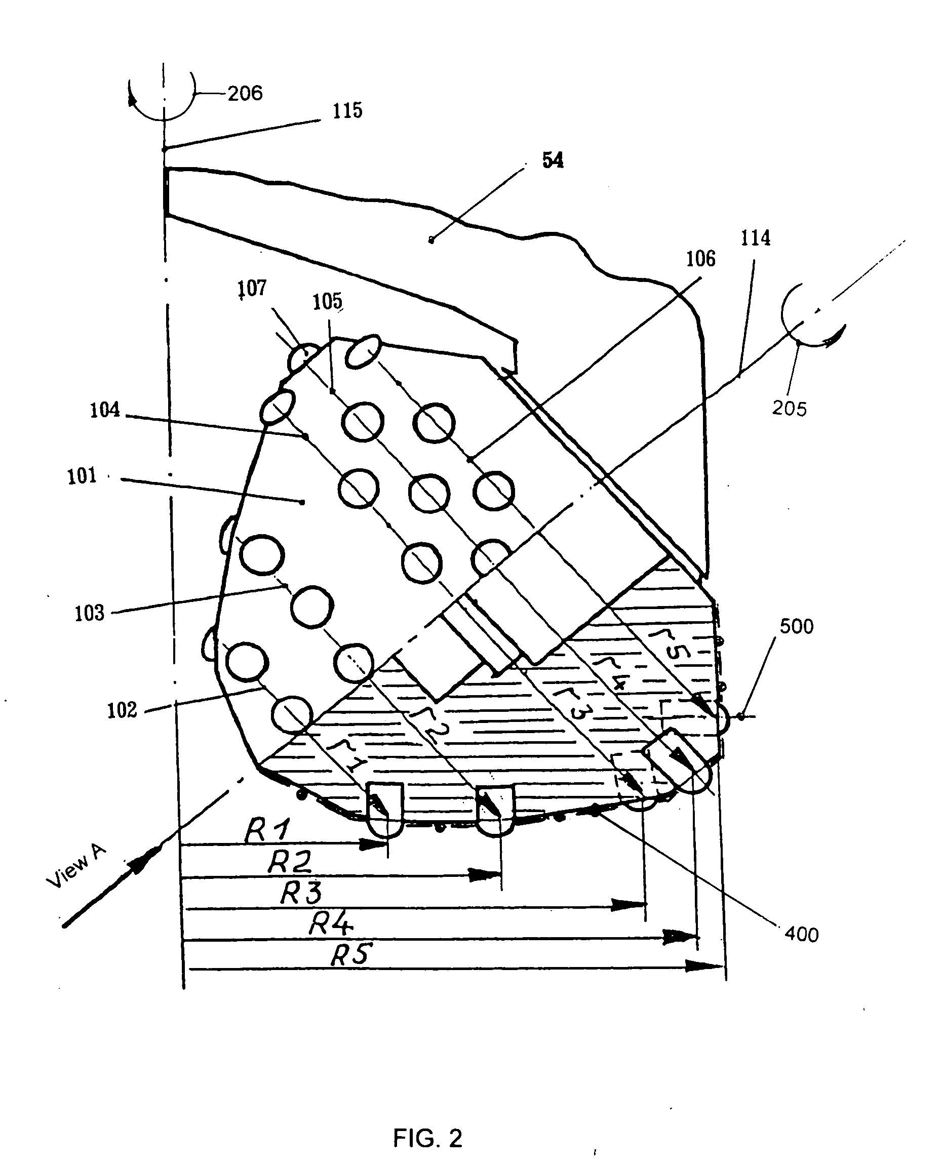
[0032] Referring now to the Figures, and specifically to FIG. 1, a conventional rolling cutter (also called rolling-cone or three-cone) drill bit 50 conventionally used for drilling a bore in an earthen formation is illustrated. Bit 50 is typical of those contemplated by the present invention. Bit 50 comprises a bit body 51 that is threaded at its upper extent 52 for connection into a drill string. Bit 50 optionally may be provided with a lubricant compensator 53. A nozzle 55 is provided in bit body 51 to cool and lubricate the drill bit during drilling. Bearing pins or arms 54 extend from bit body in a cantilevered, downwardly depending fashion. At least one cutter 101 is mounted on bit arm 54 and is carried for rotation by each section of bit body with a plurality of cutting elements 107 thereon arranged in generally circumferential rows. Tungsten-carbide inserts 107 are secured by interference fit in holes or apertures formed in cutters 101 to define the cutting elements. The cut...


PUM


Abstract

An earth boring drill bit is constructed having rotatable cutter for forming a borehole in earth. At least one circumferential row of cutting elements is optimized to create overbreak of rock and eliminate tracking, wherein selected pitches have mathematically determined pairs and the absolute difference between the selected pitch and its pair is greater than 10% of the difference between maximum and minimum pitch for that circumferential row. Furthermore, cutting elements are placed along pre-selected generatrices with deviation from said generatrices, which is less than half the maximum pitch of circumferential rows occupied by said cutting element. The present invention eliminates tracking and reduces detrimental axial resonance frequency vibration while reducing cutting element count, including tungsten-carbide inserts, as compared to conventional roller cutter drill bits used for oil, gas and shot hole drilling wells and simultaneously increases footage drilled, drilling speed, and durability.

Description

BACKGROUND OF THE INVENTION [0001] 1. Technical Field [0002] The present invention is related to drill bits for boring earthen formations. The present invention is particularly adapted for rolling cutter earth-boring bits most typically used in oil and gas drilling, but also has application in bits used in blast hole and mining applications. [0003] 2. Summary of the Prior Art [0004] In 1909, Howard R. Hughes invented the rolling cutter rock bit, which revolutionized the exploration and drilling of oil and gas wells. Since that time, countless improvements have been made to Hughes' basic design. [0005] One problem that remains to be solved is that of “tracking.” Tracking occurs when a cutting element (tungsten-carbide insert or steel tooth) falls in the same impression that was made previously by the same or another cutting element. This results in loss of drilling efficiency since the primary mode of contact between cutters and formation is between the surface of the cutter and form...

Claims


Application Information

Patent Timeline
IPC IPC(8): E21B10/08E21B10/16
CPCE21B10/16E21B10/00
Inventor AARON, ANNA VICTOROVNALYTVYNENKO, VIKTOR
Owner AARON ANNA VICTORVNA
Why Eureka
Try Eureka