Hydraulic clutch actuator for limited slip differential assembly

a clutch actuator and limited slip technology, applied in the direction of fluid couplings, gearings, couplings, etc., can solve the problems of affecting the performance of the abs feature, and unsuitable types of differentials known in the art as open differentials

Inactive Publication Date: 2005-08-04
DANA AUTOMOTIVE SYST GRP LLC
View PDF15 Cites 28 Cited by
  • Summary
  • Abstract
  • Description
  • Claims
  • Application Information

AI Technical Summary

Benefits of technology

[0028] In normal operation conditions, the control valve 40 is closed, thus preventing the flow of the pressurized hydraulic fluid from the hydraulic accumulator 36 to the piston assembly 42 and keeping the clutch assembly 30 in the disengaged condition. However, when a control algorithm determines a need for locking the differential assembly 20, the electronic control module 44 opens the solenoid-operated control valve 40 to directs the flow of the pressurized hydraulic fluid from the hydraulic accumulator 36 to the piston assembly 42 through the second communication passage 108 and the delivery pa

Problems solved by technology

However, these types of differentials known in the art as an open differentials, i.e. a differential without clutches or springs, are unsuitable in slippery conditions where one wheel experiences a much lower coefficient of friction than the other wheel; for instance, when one wheel of a vehicle is located on a patch of ice or mud and the other wheel is on dry pavement.
In such a condition, the wheel experiencing the lower coefficient of friction loses traction and a small amount of torque to that wheel will cause a “spin out” of that wheel.
The limited slip feature may

Method used


Image

  • Hydraulic clutch actuator for limited slip differential assembly
  • Hydraulic clutch actuator for limited slip differential assembly
  • Hydraulic clutch actuator for limited slip differential assembly

Examples


Embodiment Construction

[0017] The preferred embodiment of the present invention will now be described with the reference to accompanying drawings.

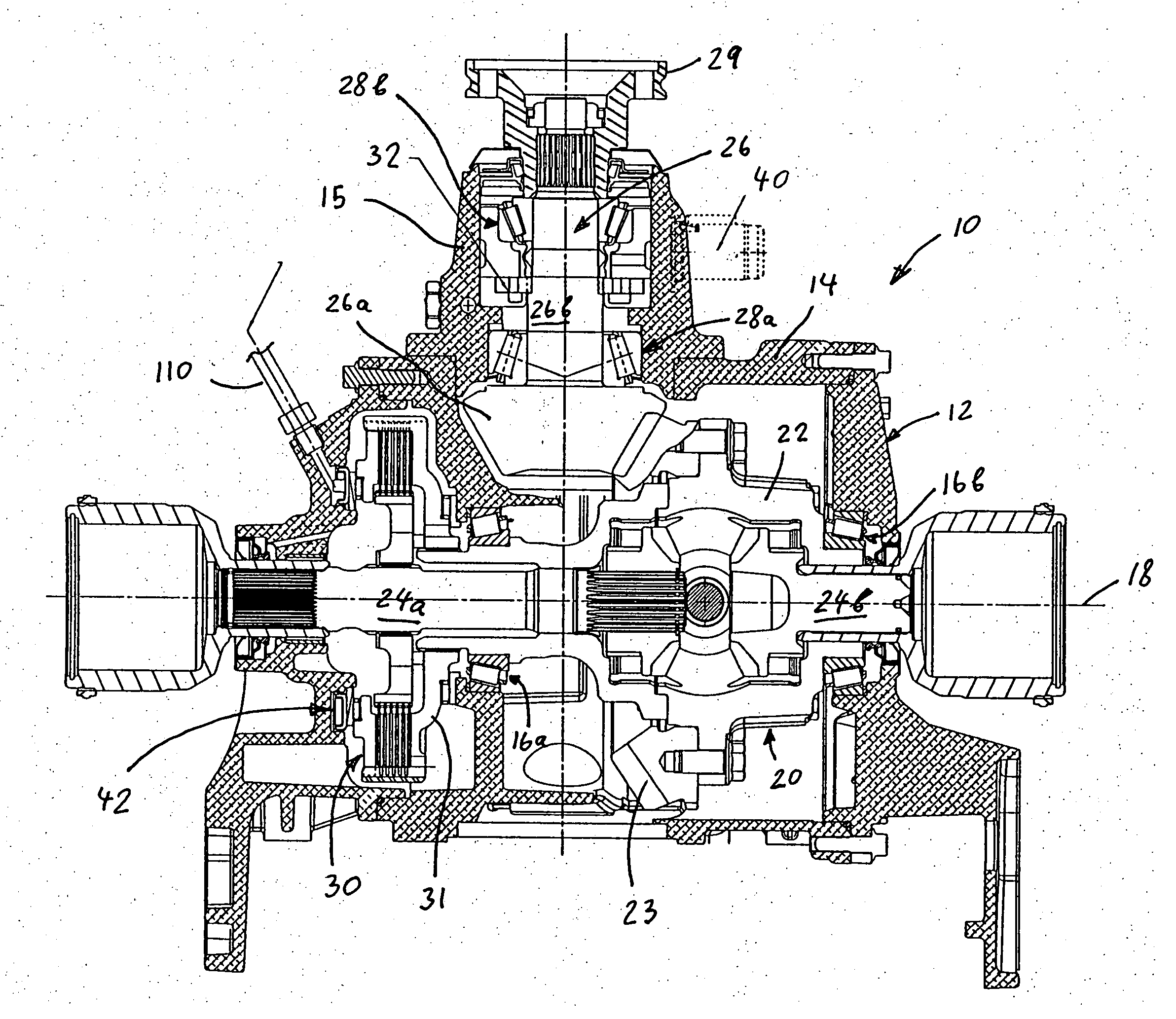
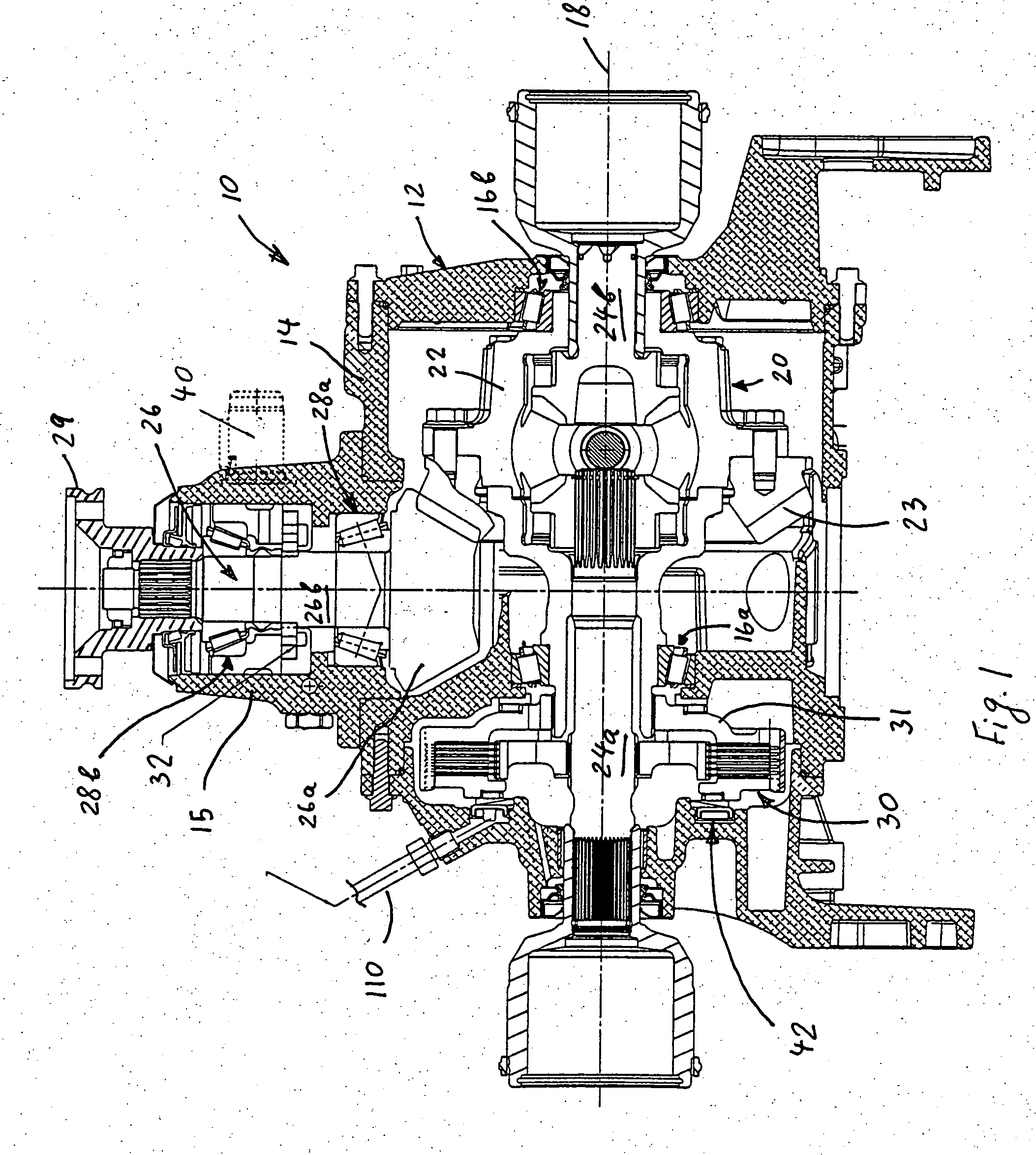
[0018]FIGS. 1 and 2 depicts a torque transmitting apparatus in the form of a vehicle drive axle assembly 10 including a selectively operable limited slip differential (LSD) assembly 20. However, it is to be understood that while the present invention is described in relation to the limited slip differential of the vehicle drive axle assembly, the present invention is equally suitable for use in any torque transmitting gear assembly including hydraulically actuated friction couplings.

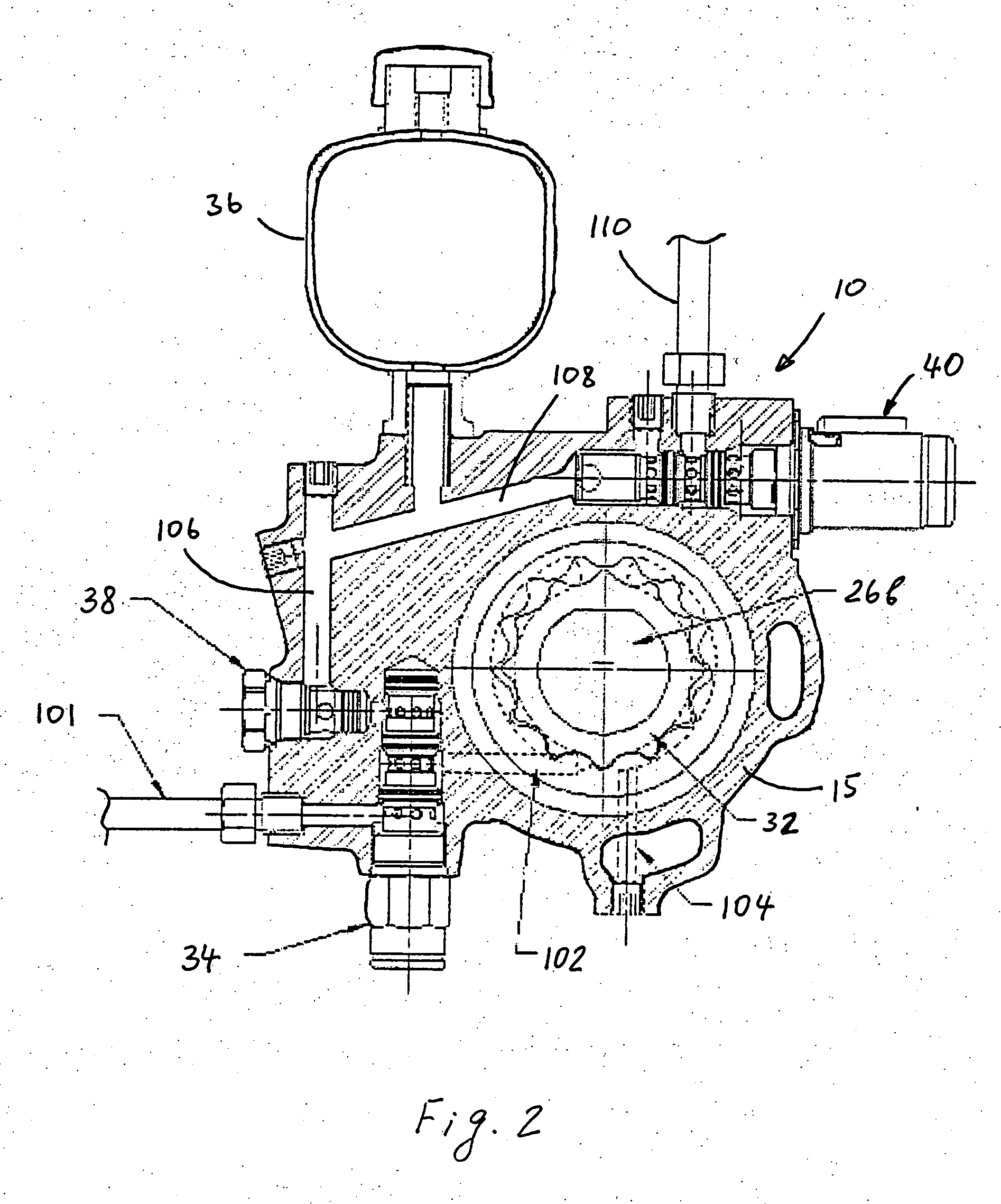
[0019] The drive axle assembly 10 comprises an axle housing 12 operatively secured to a vehicle body (not shown). The axle housing 12 includes a differential housing portion 14 rotatably supporting the differential assembly 20, and a substantially tubular neck portion 15 extending from the differential housing portion 14 for rotatably supporting an input shaft in the form of a driv...


PUM


Abstract

A torque transmitting apparatus for a motor vehicle comprises a housing rotatably supporting a differential assembly including a differential case and at least one output shaft. The torque transmitting apparatus further comprises at least one friction clutch assembly for selectively engaging and disengaging the differential case and the at least one output shaft, and a hydraulic clutch actuator for operating the at least one friction clutch assembly between a disengaged condition and an engaged condition. The hydraulic clutch actuator includes a hydraulic pump providing a hydraulic fluid under pressure and a hydraulic pressure accumulator selectively communicating with the pump for charging the accumulator with the hydraulic fluid under pressure. The hydraulic accumulator is provided for selectively communicating with the at least one friction clutch assembly for selectively setting the clutch assembly in the engaged condition.

Description

BACKGROUND OF THE INVENTION [0001] 1. Field of the Invention [0002] The present invention relates to torque transmitting apparatuses, and more particularly to a limited slip differential assembly for motor vehicles having at least one friction clutch assembly and a hydraulic clutch actuator including a hydraulic pump and a hydraulic pressure accumulator. [0003] 2. Description of the Prior Art [0004] Conventionally, differentials well known in the prior art, are arranged in a power transmission system of a motor vehicle to allow a pair of output shafts operatively coupled to an input shaft to rotate at different speeds, thereby allowing the wheel associated with each output shaft to maintain traction with the road while the vehicle is turning. Such a device essentially distributes the torque provided by the input shaft between the output shafts. However, these types of differentials known in the art as an open differentials, i.e. a differential without clutches or springs, are unsuit...

Claims


Application Information

Patent Timeline
IPC IPC(8): F16H48/08F16H48/22F16H48/30
CPCF16H48/08F16H48/22F16H48/30F16H2200/2071F16H48/34F16H2048/204F16H2048/423F16H48/32
Inventor BAXTER, RALPH W. JR.
Owner DANA AUTOMOTIVE SYST GRP LLC
Why Eureka
Try Eureka