
Monitoring apparatus

a technology of monitoring apparatus and auxiliary components, which is applied in the direction of instruments, material analysis through optical means, photoelectric discharge tubes, etc., can solve the problems of reducing the size of the encoder, reducing the efficiency of the instrument, so as to increase the size of the apparatus and reduce the cost.

Inactive Publication Date: 2005-08-04
FANUC LTD
View PDF11 Cites 4 Cited by
  • Summary
  • Abstract
  • Description
  • Claims
  • Application Information

AI Technical Summary

Benefits of technology

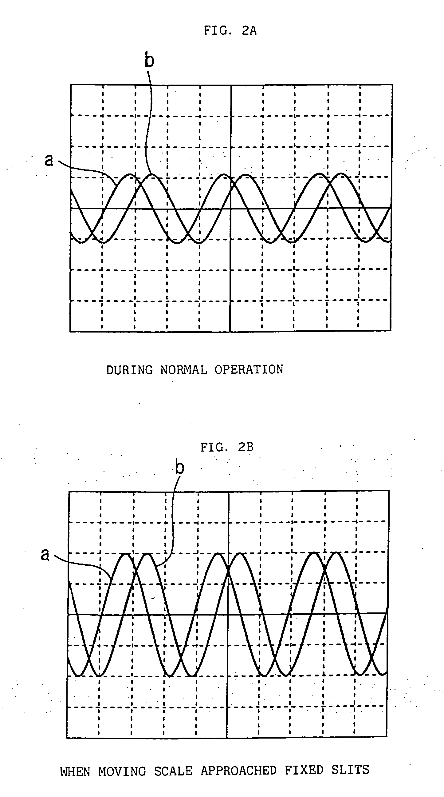
This patent describes a monitoring apparatus that uses an optical encoder to detect changes in the distance between fixed slits and a moving scale, which is connected to a motor. The monitoring apparatus monitors the amplitude of a light receiving element and detects a displacement between the moving scale and fixed slits based on the monitoring result. This allows for the detection of excessive load or displacement without the need for a separate sensor, which can save costs and avoid complicated structures. The monitoring apparatus can also detect an excessive load or displacement in a perpendicular direction relative to the position reading direction of the encoder or the direction of movement of the motor.

Problems solved by technology

For example, in a case where an encoder is attached to an air bearing motor, when an excessive load is applied in a direction perpendicular to a position reading direction of the moving scale or a direction of movement (rotational direction) of a moving part of the motor, an air bearing surface of the stator and the rotor come into contact, and in the worst case this can result in destruction of the motor.
However, incorporating a separately provided displacement sensor or the like into an optical encoder makes the size of the encoder larger and complicates the structure thereof.
It is also disadvantageous in terms of cost.

Method used


Image

  • Monitoring apparatus
  • Monitoring apparatus
  • Monitoring apparatus

Examples


Embodiment Construction

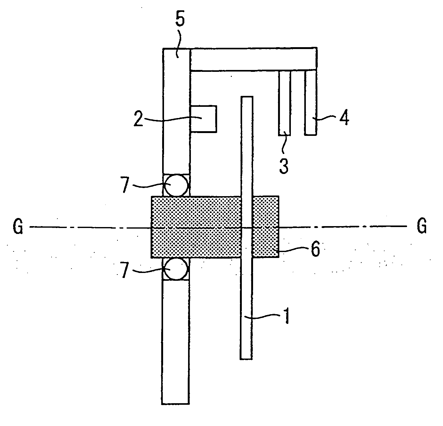
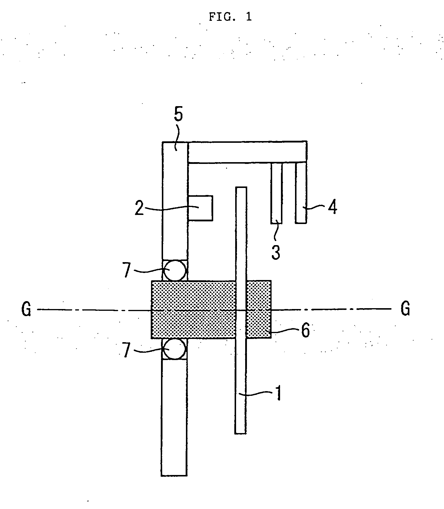
[0022]FIG. 1 is a sectional view showing an outline of the structure of an optical encoder to which the monitoring apparatus according to this invention is applied.

[0023] In FIG. 1, reference numeral 1 denotes a disc-shaped moving scale on which an optical code is formed in a known manner in a pattern of light transmitting area / nontransparent area, and the moving scale 1 is supported on a moving scale support member 6. The moving scale support member 6 is attached to an object that is the subject of detection (target object for detection of position and speed), such as a rotating shaft of a motor, or alternatively one part of the object that is the subject of detection itself comprises the moving scale support member 6.

[0024] A light source part denoted by reference numeral 2 comprises, for example, one or a plurality of LEDs, and irradiates light onto the moving scale 1. The light source part 2 emits light by a light emission driving circuit (not shown). Light emitted from the li...


PUM


Abstract

An amplitude of an electrical signal generated on the basis of a light detected by a light receiving part of an optical encoder is monitored and, using the monitored result, a displacement between a moving scale and fixed slits of an optical encoder (or a displacement of a moving part in a motor attached with an optical encoder) is detected. Further, a load applied to a moving part in a motor attached with an optical encoder is detected using the monitored result.

Description

BACKGROUND OF THE INVENTION [0001] 1. Field of the Invention [0002] The present invention relates to a monitoring apparatus for an optical encoder that detects the position or speed of a motor driving, for example, a shaft of a machine tool or industrial robot or the like, as well as a monitoring apparatus for a motor to which the optical encoder is attached. [0003] 2. Description of the Related Art [0004] An optical encoder is widely used for detecting, for example, the position or speed of a servomotor driving a shaft of a machine tool or industrial robot. In general, an optical encoder is configured to receive transmitted light or reflected light that is encoded by a moving scale by means of light receiving elements through fixed slits, to form electrical signals as output of the encoder. Although a suitable clearance is provided between a moving scale and fixed slits, this clearance may sometimes fluctuate. For example, in a case where an encoder is attached to an air bearing mo...

Claims


Application Information

Patent Timeline
Patent Type & Authority Applications(United States)
IPC IPC(8): G01D5/347H02K11/00
CPCG01D5/3473
Inventor KAWAI, TOMOHIKOTANIGUCHI, MITSUYUKIODA, TAKAYUKI
Owner FANUC LTD
Learn More