Axle housing with suspension flange

a technology of axle housing and flange, which is applied in the direction of axle units, vehicle components, transportation and packaging, etc., can solve the problems of affecting the fatigue life of the axle housing, so as to achieve the effect of minimizing the thickness of the axle housing and distributing the stress

Inactive Publication Date: 2005-08-04
ARVINMERITOR TECH
View PDF6 Cites 24 Cited by
  • Summary
  • Abstract
  • Description
  • Claims
  • Application Information

AI Technical Summary

Benefits of technology

[0008] In one disclosed embodiment, each housing half is defined by a C-shaped cross section. Each housing half includes a base portion with a pair of vertically extending side walls. The suspension flanges extend transversely relative to one of the side walls and are formed generally parallel to the base portions. The flange geometry is optimized to transfer suspension loads in a manner that allows greater distribution of stress than conventional attachment methods. This allows axle housing wall thickness to be minimized.

Problems solved by technology

The suspension mount interface creates many design challenges.
It is difficult to provide attachment hardware, i.e. brackets, clamps, fasteners, etc., which can accommodate all of these different suspension mount interface variations.
Further, the fatigue life of the axle housing can be compromised or decreased in certain bracket attachment configurations.
For example, high stress concentrations can be caused by poor geometry configurations for certain types of welded suspension brackets, which results in reduced fatigue life.
Or when clamps are used, concentrated reaction areas from bolted brackets can cause high internal stresses due to cyclical deflections within the clamped joint, which causes fatigue to initiate inside the axle housing creating an “oil can effect.”
This reduces high external and internal stress concentrations but adds weight to the axle housing.
This increases cost and decreases fuel economy, making the product less competitive.

Method used


Image

  • Axle housing with suspension flange
  • Axle housing with suspension flange
  • Axle housing with suspension flange

Examples


Embodiment Construction

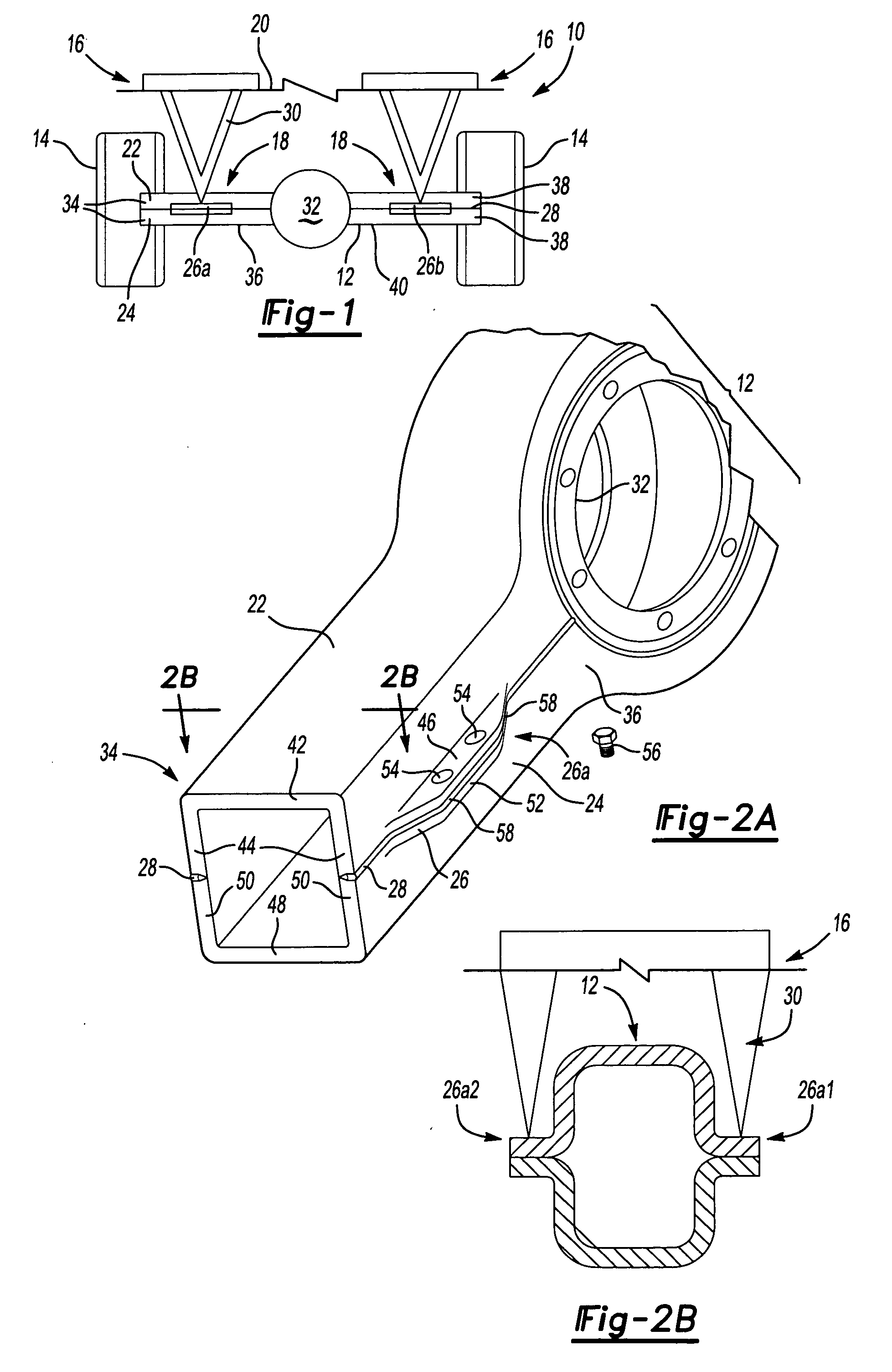
[0019] An axle assembly is shown generally at 10 in FIG. 1. The axle assembly 10 includes an axle housing 12 that supports a pair of wheels 14 on opposing ends. A vehicle suspension 16 is attached to the axle housing 12 at a suspension mount interface 18. The suspension 16 dampens or absorbs input received from the axle housing 12 via the wheels 14. The suspension 16 is positioned between the axle housing 12 and a vehicle frame 20.

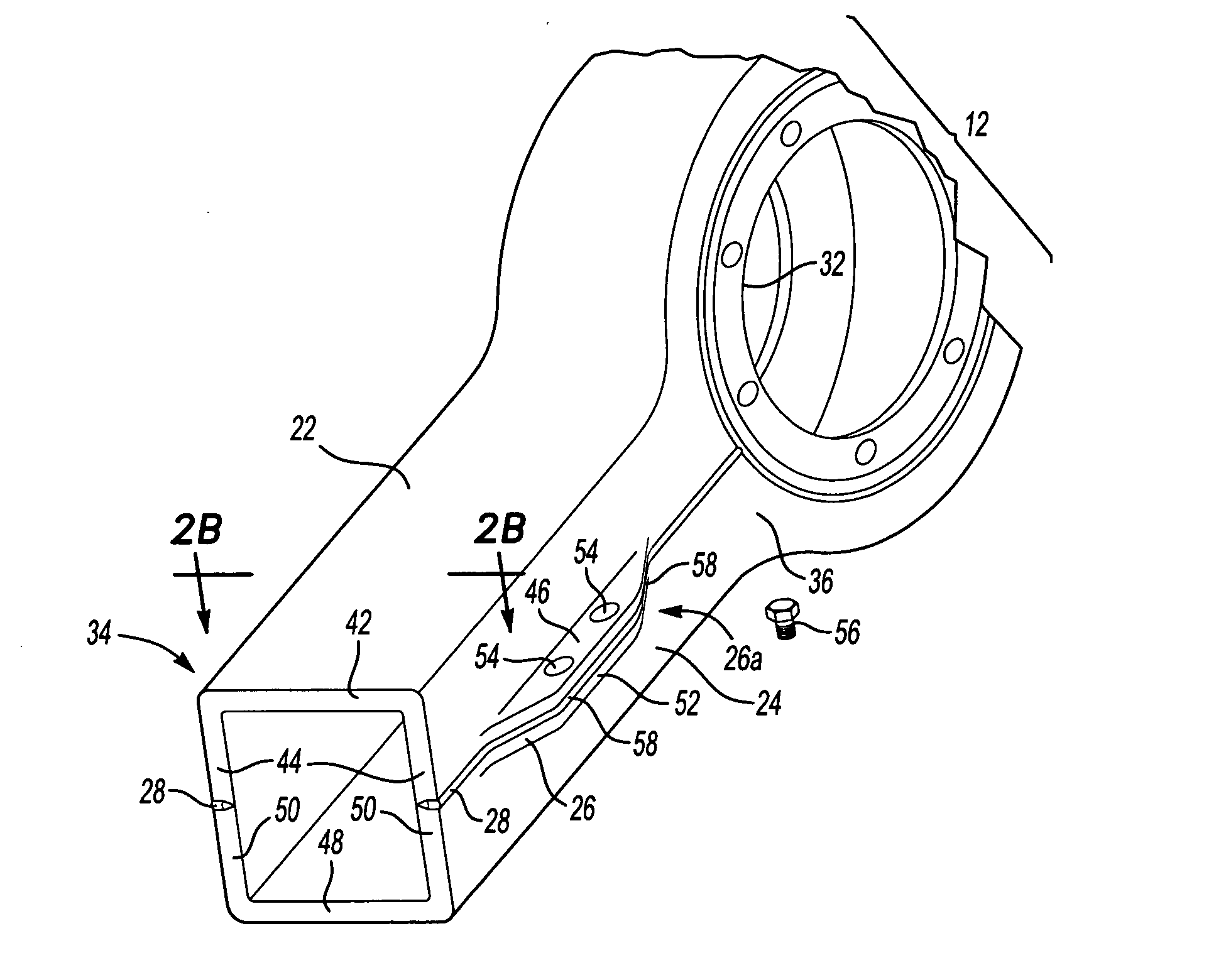
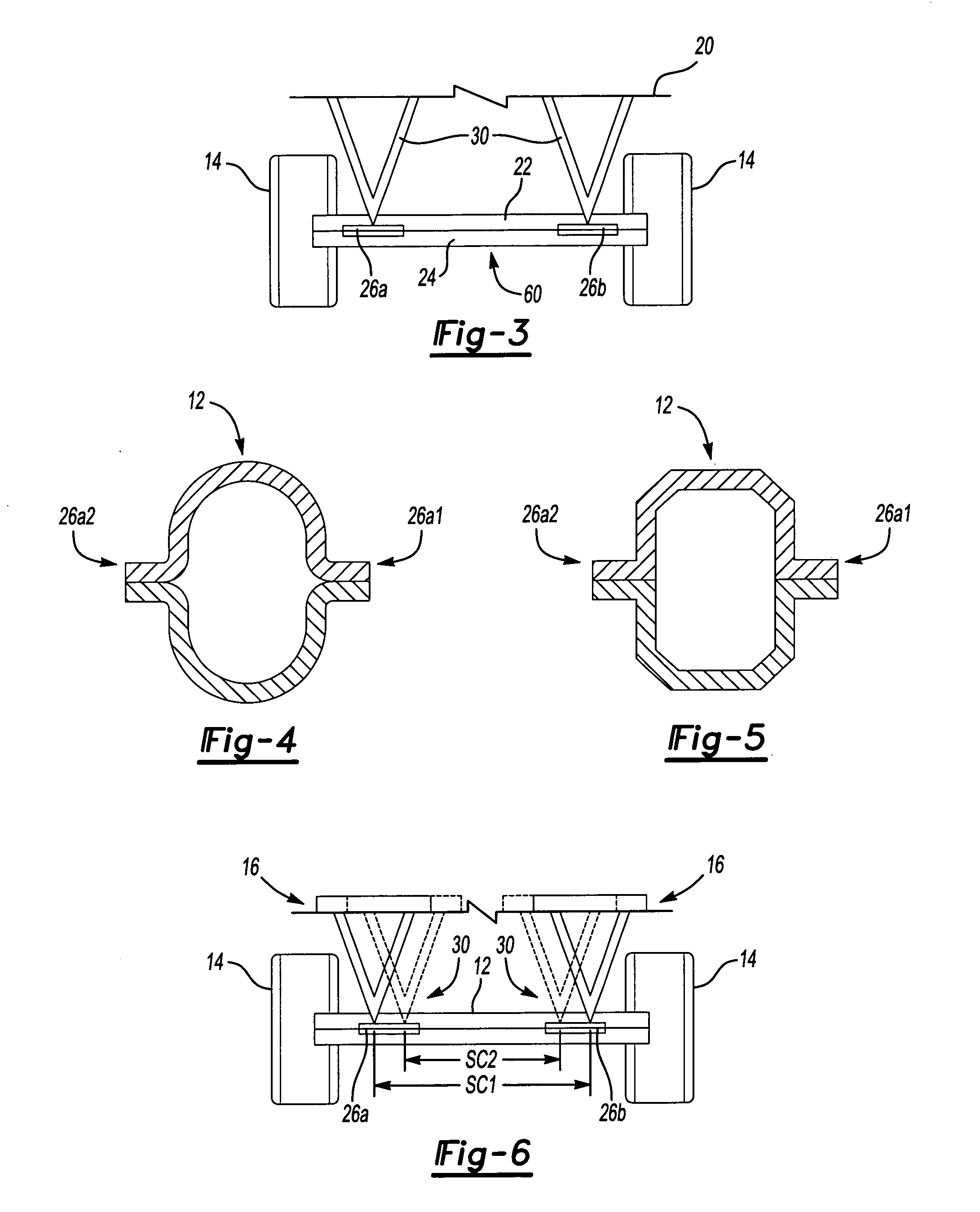
[0020] The axle housing 12 as shown in FIG. 2A includes a first housing half 22 and a second housing half 24. The housing halves 22, 24 are preferably symmetrical, however non-symmetrical halves could also be used. Suspension flanges 26 are directly or integrally formed as part of each housing half 22, 24. Preferably, the axle housing includes suspension flanges 26 on each end of the axle housing 12. A first set of suspension flanges 26a is formed on one end and a second set of flanges 26b is formed on an opposite end, see FIG. 1. Further, in one embodime...


PUM


Abstract

A suspension mount includes a flange formed directly into an axle housing. The axle housing includes a pair of housing halves that are attached to each other along a seam weld. Each housing half includes at least one transversely extending flange. Prior to welding, the flanges from the upper and lower housing halves are aligned with each other to define the suspension mount. The suspension is then attached to the axle housing at the flanges with fasteners or by welding.

Description

BACKGROUND OF THE INVENTION [0001] The subject invention generally relates to a vehicle axle housing including a suspension flange formed directly into the axle housing. [0002] Medium and heavy duty vehicles include suspensions that are attached to axle housings in various different manners. Traditionally, these suspensions are welded to an immediately adjacent or upper surface of the axle housing, or are clamped to the axle housing to define a suspension mount interface. [0003] The suspension mount interface creates many design challenges. There are a variety of suspension types and each type of suspension can have many different configurations. It is difficult to provide attachment hardware, i.e. brackets, clamps, fasteners, etc., which can accommodate all of these different suspension mount interface variations. Further, the fatigue life of the axle housing can be compromised or decreased in certain bracket attachment configurations. For example, high stress concentrations can be...

Claims


Application Information

Patent Timeline
Patent Type & Authority Applications(United States)
IPC IPC(8): B60B35/16
CPCB60B35/006B60B35/163B60B2900/321B60B2310/305B60B2310/302
Inventor ESCHENBURG, DALE J.
Owner ARVINMERITOR TECH
Why Eureka
Try Eureka