
Magneto-optical recording medium and method of manufacturing the same

Inactive Publication Date: 2005-08-04
FUJITSU LTD
View PDF6 Cites 2 Cited by
  • Summary
  • Abstract
  • Description
  • Claims
  • Application Information

AI Technical Summary

Benefits of technology

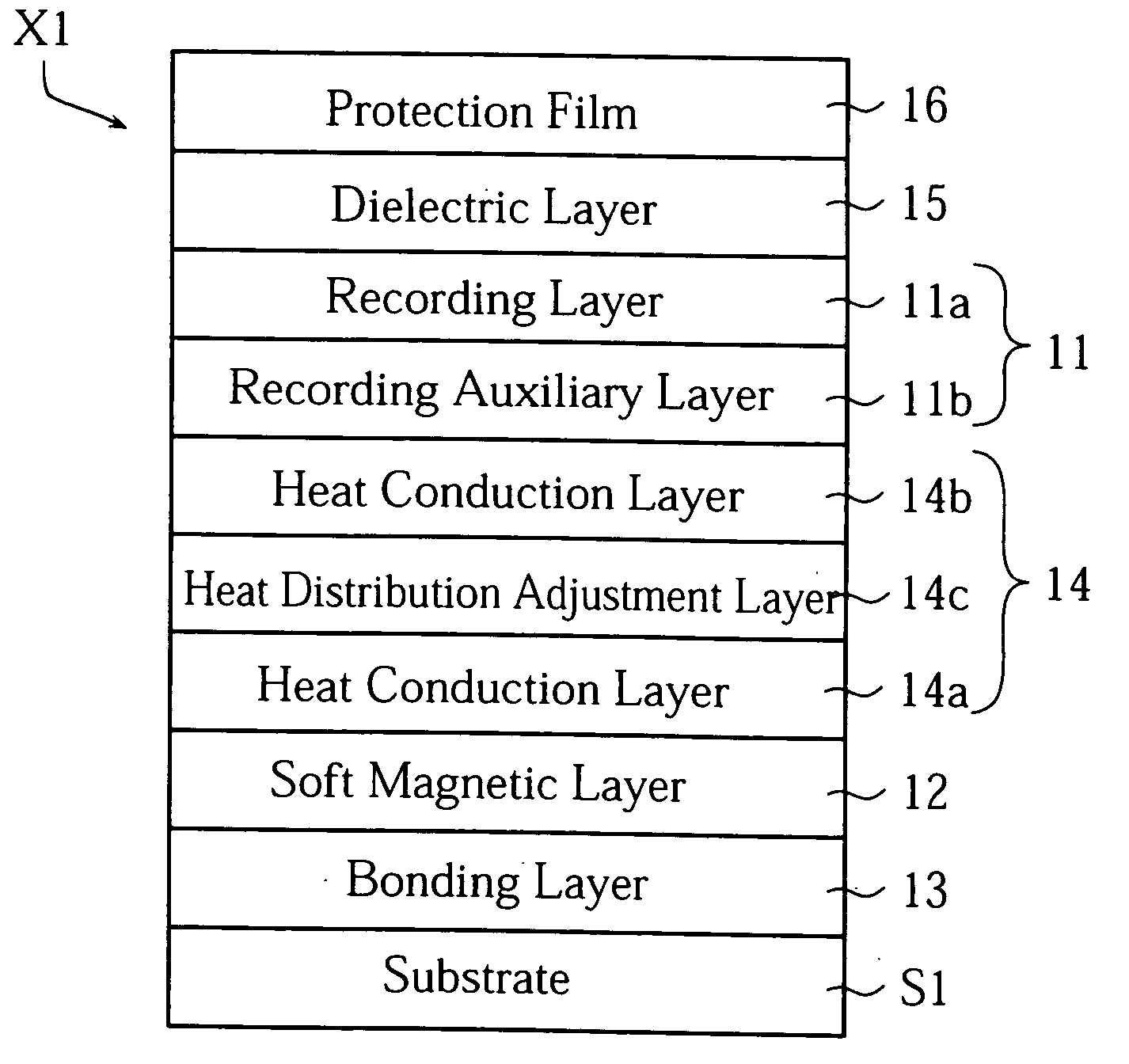
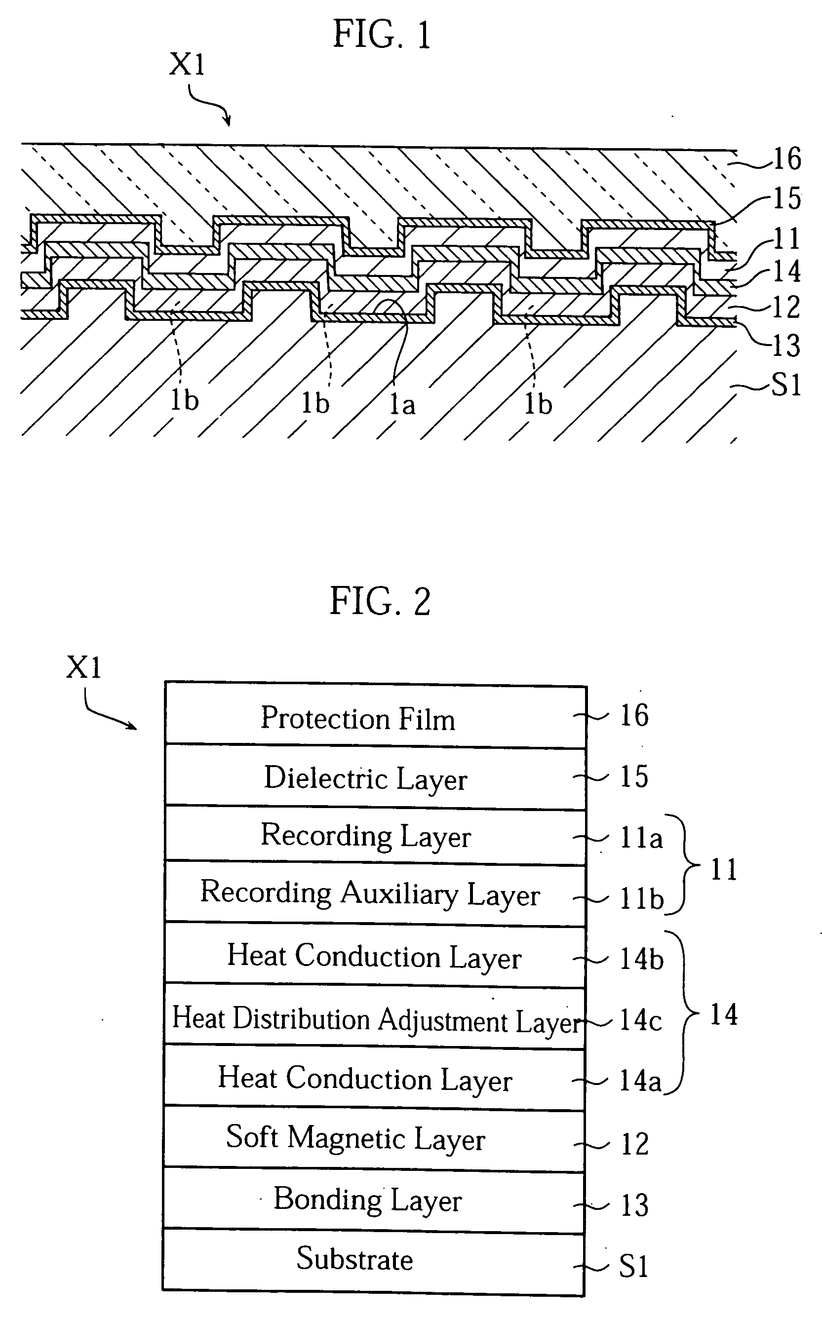
[0017] In manufacture of magneto-optical recording mediums having such a configuration, the bonding layer is formed on the resin substrate, and the soft magnetic plating layer is then formed on the bonding layer with a plating method. The bonding layer provides superior attachment with the substrate of the synthetic resin material, and superior attachment with the plated film of soft magnetic material. For example, AlCr, Al, Cr, Ti, FeCo, Ni, NiP, Pd, SiN, and SiO2 may be employed as this material. Since the bonding layer is interposed between the soft magnetic plating layer and the resin substrate, it is possible to obtain satisfactory attachment between the soft magnetic plating layer and the resin substrate in the magneto-optical recording medium.
[0034] According to such a method, the magneto-optical recording medium according to the second aspect of the present invention can be appropriately manufactured. According to the fifth aspect of the present invention, therefore, the advantages described above in relation to the second aspect can be demonstrated in the manufactured magneto-optical recording medium. Furthermore, according to the fifth aspect, since the electroless deposition method is employed as a method of forming the soft magnetic plating layer included in the recording magnetic section, satisfactory throughput can be realized in formation of the soft magnetic layer.

Problems solved by technology

Since this transparent substrate is required to be of considerable thickness to ensure stiffness of the medium, use of a lens having a short focal distance, in other words, a large numerical aperture NA, becomes difficult for a back-illuminated magneto-optical recording medium.
However, when the substrate S3 is made of synthetic resin, the soft magnetic layer 92 often fails to be formed properly on the substrate S3 by the sputtering method, as opposed to the conventional case in which the sputtering is appropriate for forming the soft magnetic layer 92.
However, since the difference in the thermal expansion coefficients of the synthetic resin material and the soft magnetic material is large, the soft magnetic layer 92, which contracts to a smaller degree than the substrate S3, is subject to undesirable stress.
However, when a resin substrate is employed as the substrate S3, and the film of soft magnetic material is formed directly on the resin substrate with the electroless deposition method, the resultant soft magnetic plating layer and the resin substrate are not attached to each other sufficiently to withstand practical use of the magneto-optical recording medium.

Method used


Image

  • Magneto-optical recording medium and method of manufacturing the same
  • Magneto-optical recording medium and method of manufacturing the same
  • Magneto-optical recording medium and method of manufacturing the same

Examples


example 1

[0100] A magneto-optical recording medium of the present example was manufactured as a front-illuminated magneto-optical disk having the laminated configuration as shown in FIG. 12.

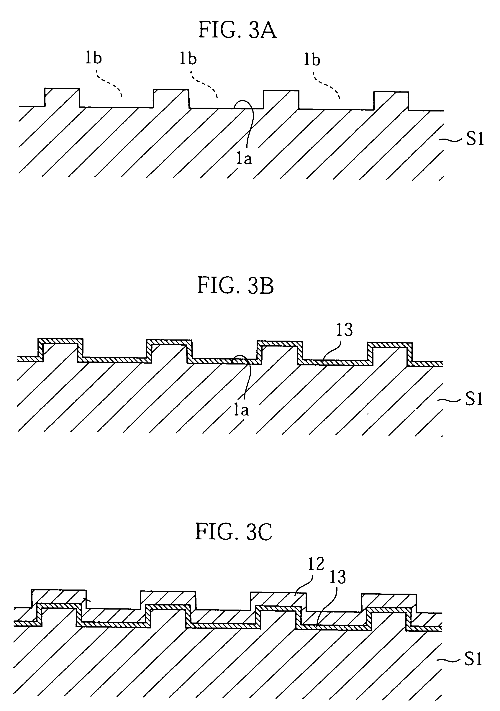
[0101] In manufacture of the magneto-optical recording medium of the present example, firstly, spiral-shaped pre-grooves were manufactured in the surface of a polycarbonate substrate (diameter: 86 mm, thickness: 1.2 mm, land width: 0.275 μm, groove width: 0.275 μm, groove depth: 50 nm). Specifically, an Ni stamper having a spiral pattern on its surface of 50 nm in depth and 0.275 μm track pitch was placed in a metal mold, and the substrate is formed by injecting synthetic resin into the mold.

[0102] Next, a bonding layer of 30 nm in thickness was formed by using a DC magnetron sputtering apparatus to form a Ti film on the pre-groove surface of the substrate with the DC sputtering method. This sputtering employed a Ti target and Ar gas as the sputter gas, with a sputter gas pressure of 0.5 Pa, and dischar...

example 2

[0117] A magneto-optical recording medium of the present example was manufactured as a front-illuminated magneto-optical disk having the laminated configuration as shown in FIG. 13.

[0118] In manufacture of the magneto-optical recording medium of the present example, firstly, a flat polycarbonate substrate (diameter: 86 mm, thickness: 1.2 mm) was manufactured for application of a bonding layer. Specifically, a flat Ni stamper without pre-grooves was placed in a metal mold, and the substrate formed by injecting synthetic resin into the mold.

[0119] Next, a bonding layer (Ti, thickness: 30 nm) and a soft magnetic layer (CoNiFe, thickness: 1000 nm) were formed on the flat surface of the substrate in the same manner as with Example 1.

[0120] Next, UV cure resin (Yupima, manufactured by Mitsubishi Chemical Corporation) was applied to the soft magnetic layer, and a stamper transparent to the synthetic resin affixed to the soft magnetic layer. This transparent stamper has a spiral pattern ...


PUM


Abstract

The magneto-optical recording medium (X1) includes a resin substrate (S1) having a pre-groove surface (1a) on which pre-grooves (1b) are formed, a recording magnetic section (11) performing a recording function and a reproduction function, a soft magnetic plating layer (12) provided between the resin substrate (S1) and the recording magnetic section (11), and a bonding layer (13) interposed between the resin substrate (S1) and the soft magnetic plating layer (12) for enhancing attachment between the resin substrate (S1) and the soft magnetic plating layer (12).

Description

TECHNICAL FIELD [0001] The present invention relates to a magneto-optical recording medium having a soft magnetic layer, and a method of manufacturing such a magneto-optical recording medium. BACKGROUND ART [0002] Magneto-optical recording mediums have been the subject of much attention in recent years. Magneto-optical recording mediums employ a variety of magnetic properties of magnetic materials, and are rewritable recording mediums having two functions of thermomagnetic recording and reproduction employing magneto-optical effects. Magneto-optical recording mediums have a recording magnetic section comprising one or more perpendicularly magnetized films. Signals are recorded on the recording layer in the recording magnetic section. During recording, the prescribed location on the recording layer is heated by illumination with a laser focused via an objective lens while the prescribed magnetic field is applied at the relevant location. Thus, the prescribed signals are recorded as c...

Claims


Application Information

Patent Timeline
IPC IPC(8): G11B7/24G11B11/105
CPCG11B11/10582G11B11/10586G11B11/10584
Inventor UMADA, TAKAHIROMORIBE, MINEO
Owner FUJITSU LTD
Learn More