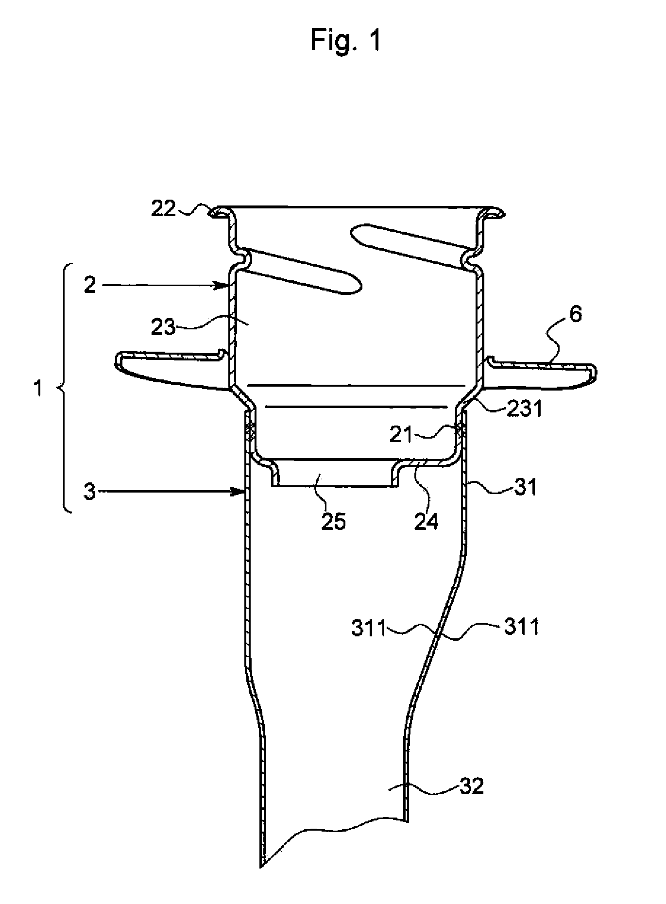
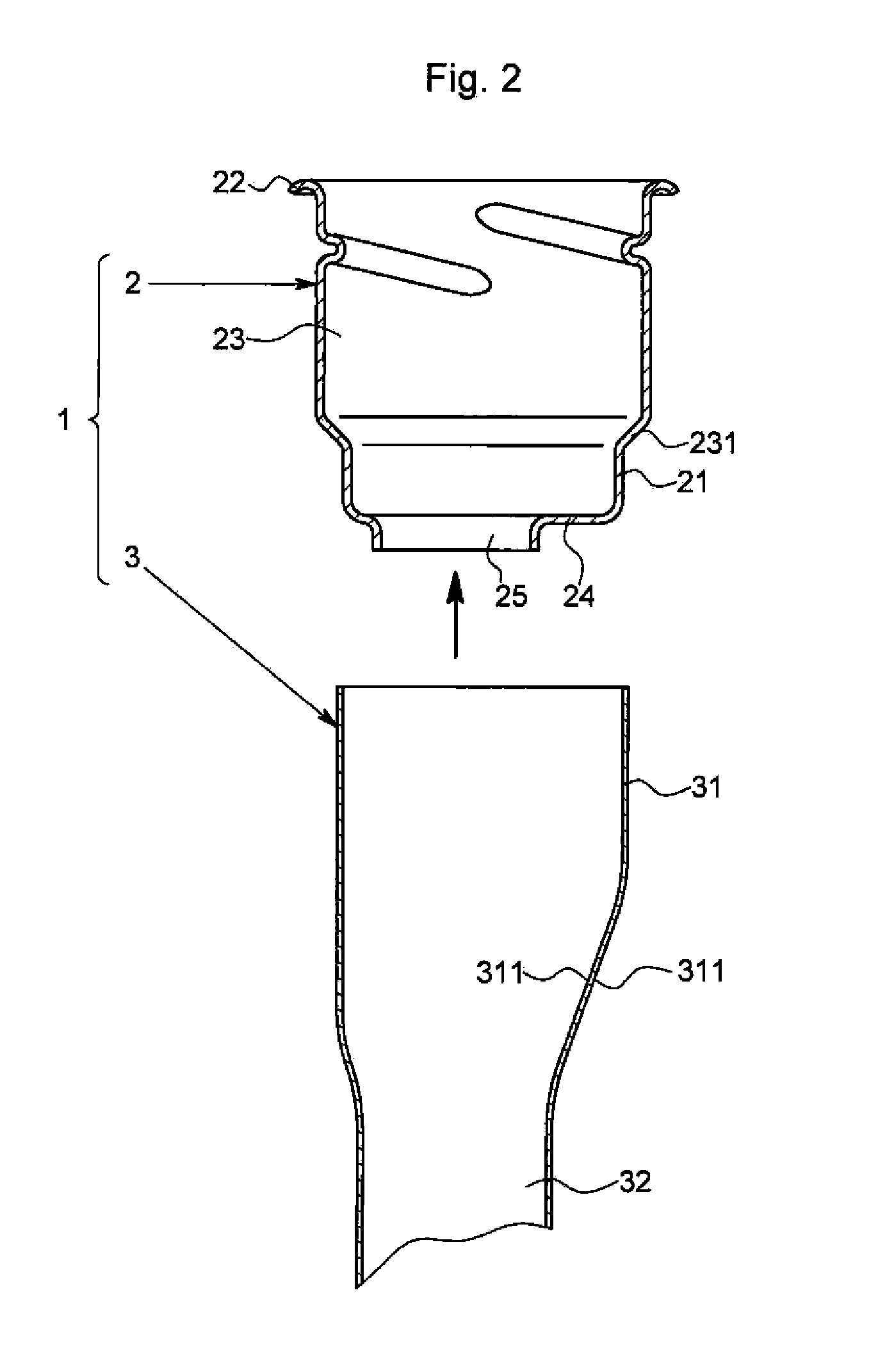
Manufacturing Method of Fuel Filler Tube
a fuel filler and manufacturing method technology, applied in the direction of manufacturing tools, curved planar seam welding, welding with roller electrodes, etc., can solve the problems of easy generation of grain boundary corrosion in stainless steel plates, easy formation of rust, and easy generation of zinc oxide and white rust. , to achieve the effect of enhancing the rust prevention performance of the entire inlet pipe, easy formation, and satisfactory attachment of rust preventing pain
- Summary
- Abstract
- Description
- Claims
- Application Information
AI Technical Summary
Benefits of technology
Problems solved by technology
Method used
Image


Examples
example
[0037]The effectiveness of the rust preventing effect according to the present invention will be more specifically described with reference to examples and comparative examples.
[0038]The salt spray test compliant with JIS Z 2371 was conducted on a test piece (comparative example 1) in which the stainless steel plates were seam welded and test pieces (comparative examples 2 and 3, example 1) in which the stainless steel plate and the zinc plated steel plate were seem welded to verify the relationship between the thickness of the plated layer and the presence of rust occurrence. When carrying out the seam welding, the width of the roller electrodes was made smaller than the surface contacting region of the steel plate. The roller electrodes were pressed to the surface contacting region at 0.18 MPa, where the welding current was 7,500 A, the welding speed was 15 cm / s, and the plate thickness of the test piece was 1.2 mm. The SUS 436 used for the general automobile parts was used for th...
PUM
| Property | Measurement | Unit |
|---|---|---|
| thickness | aaaaa | aaaaa |
| temperature | aaaaa | aaaaa |
| normal electrode potential | aaaaa | aaaaa |
Abstract
Description
Claims
Application Information
PatSnap Eureka turns technology decisions into work you can execute. Powered by our Innovation Knowledge Graph, it runs expert workflows across engineering, life sciences, materials and intellectual property. Get your review-ready output in minutes.


