Method and apparatus for optical disc playback
a technology of optical discs and playback equipment, applied in the direction of digital signal error detection/correction, instruments, recording signal processing, etc., can solve the problems of large amplitude turbulence of te signal (d), large turbulence of te signal, and undesirable effects, so as to improve the vibration resistance during playback
- Summary
- Abstract
- Description
- Claims
- Application Information
AI Technical Summary
Benefits of technology
Problems solved by technology
Method used
Image
Examples
first embodiment
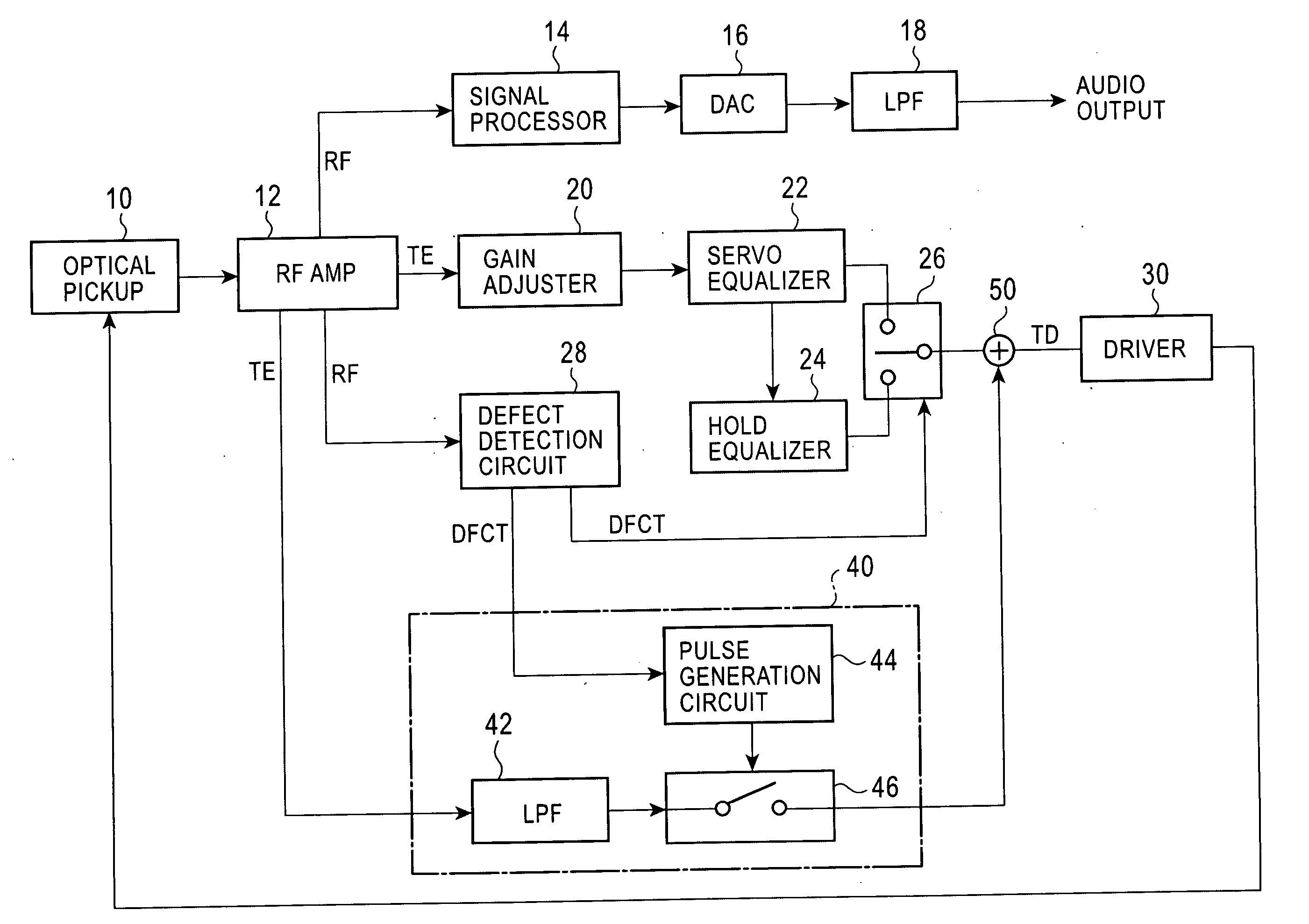
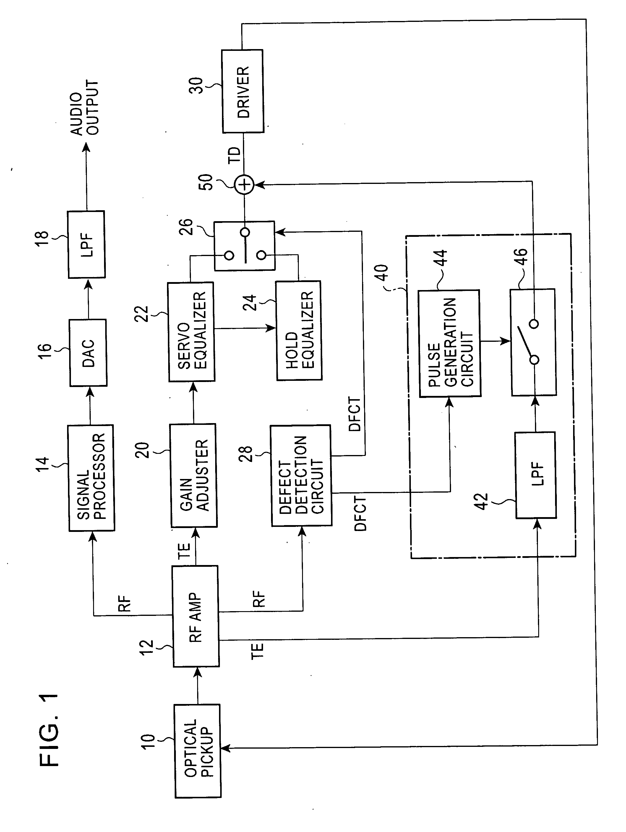
[0032]FIG. 1 is a block diagram of an optical disc playback apparatus according to a The same parts as those of the optical disc playback apparatus shown in FIG. 7 are given the same reference numerals. As shown in FIG. 1, the optical disc playback apparatus includes an optical pickup 10 and an RF amplifier 12. The optical pickup 10 irradiates a recording surface of an optical disc with laser light, and converts the reflected light into an electrical signal. The RF amplifier 12 receives the electrical signal from the optical pickup 10, and generates an RF playback signal, a tracking error signal (TE signal), etc. The signal output from the RF amplifier 12 is audibly output via a signal processor 14, a digital-to-analog converter (DAC) 16, and a low-pass filter (LPF) 18, and is converted into an audible sound by a speaker.
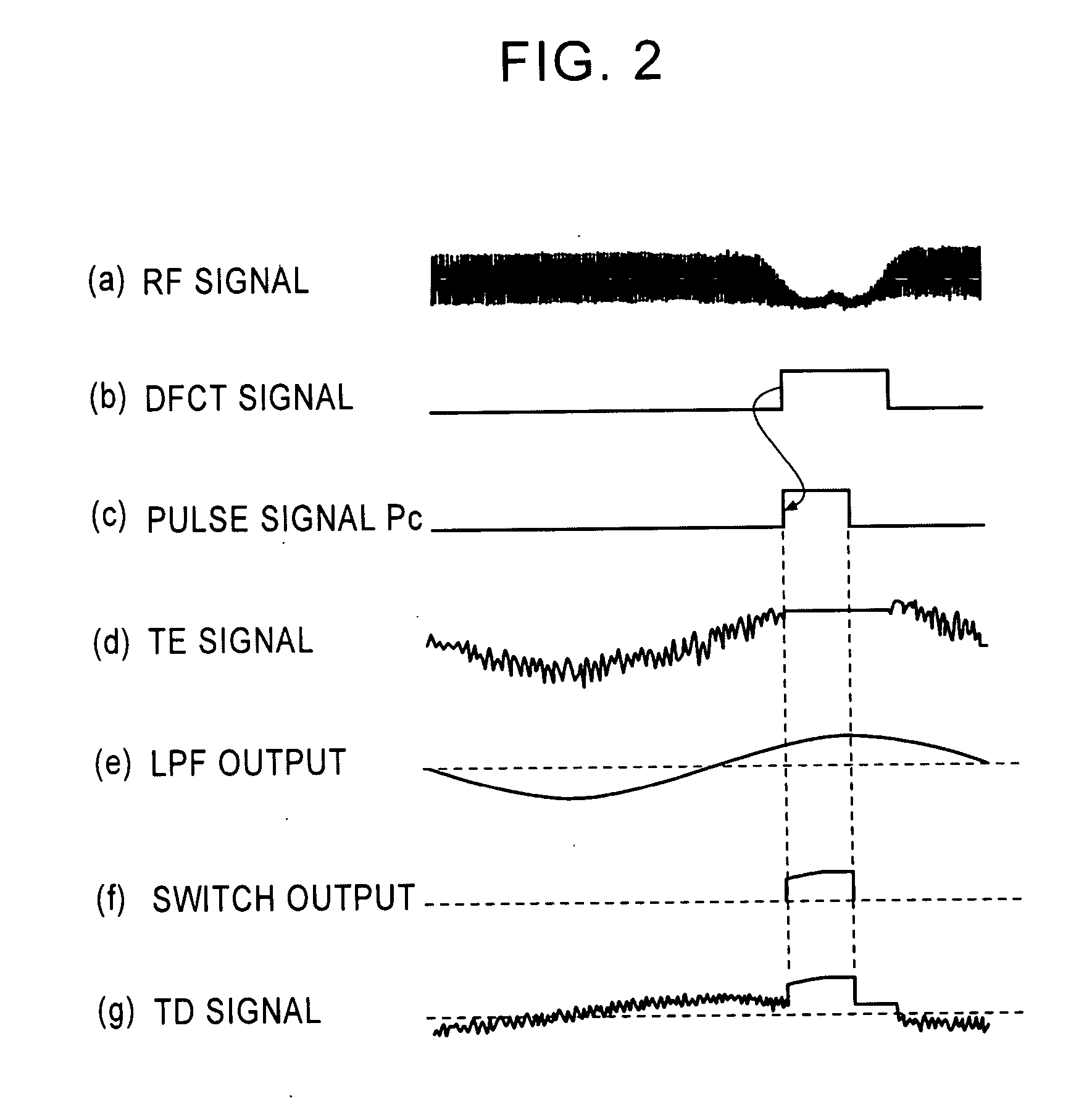
[0033] In order to perform tracking servo on the optical pickup 10, the TE signal from the RF amplifier 12 is supplied as a tracking driving signal (TD signal) to ...
second embodiment
[0051] In the second embodiment, the corrector 40 further includes a pulse width control circuit 48 for varying the width of the pulse signal output from the pulse generation circuit 44. The pulse width control circuit 48 includes an AND circuit that carries out the logical AND between a pulse signal Pc from the pulse generation circuit 44 and a DFCT signal, and controls the pulse width corresponding to the size of a defect on an optical disc.
[0052]FIGS. 6A and 6B are waveforms showing that a disc having a large scratch width and a disc having a small scratch width are played back by the optical disc playback apparatus of the second embodiment, respectively.
[0053] The larger the scratch width, the longer the period of time during which the RF signal falls, as indicated by (a). Thus, as indicated by (b), the pulse width of the DFCT signal becomes longer. The pulse generation circuit 44 outputs a pulse signal Pc having a constant pulse width, as indicated by (c). The pulse width cont...
PUM
 Abstract
Description
Claims
Application Information
 - R&D
- Intellectual Property
- Life Sciences
- Materials
- Tech Scout
- Unparalleled Data Quality
- Higher Quality Content
- 60% Fewer Hallucinations
Browse by: Latest US Patents, China's latest patents, Technical Efficacy Thesaurus, Application Domain, Technology Topic, Popular Technical Reports.
© 2025 PatSnap. All rights reserved.Legal|Privacy policy|Modern Slavery Act Transparency Statement|Sitemap|About US| Contact US: help@patsnap.com


