Timing error recovery system

a technology of error recovery and time, applied in the direction of digital transmission, transmission monitoring, electrical equipment, etc., can solve the problems of error signal and still significant signal error

Inactive Publication Date: 2005-08-04
AGERE SYST INC
View PDF12 Cites 21 Cited by
  • Summary
  • Abstract
  • Description
  • Claims
  • Application Information

AI Technical Summary

Problems solved by technology

This results in an error signal, which the PLL then uses to correct the sampling rate.
While use of a PLL reduces signal error, there is still significant error in the signal.

Method used


Image

  • Timing error recovery system
  • Timing error recovery system
  • Timing error recovery system

Examples


Embodiment Construction

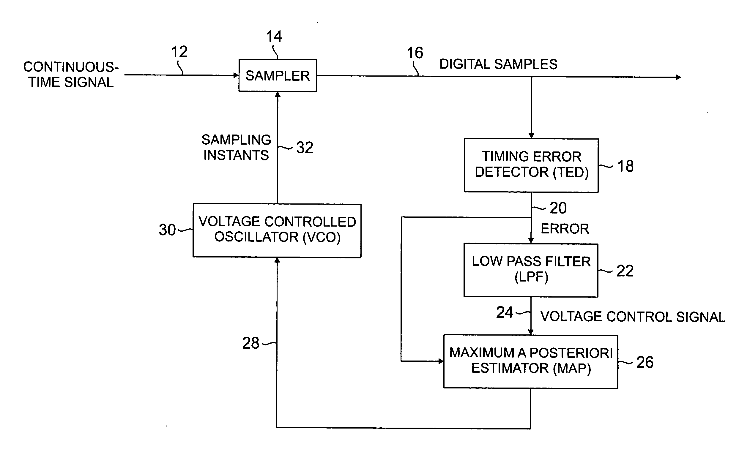
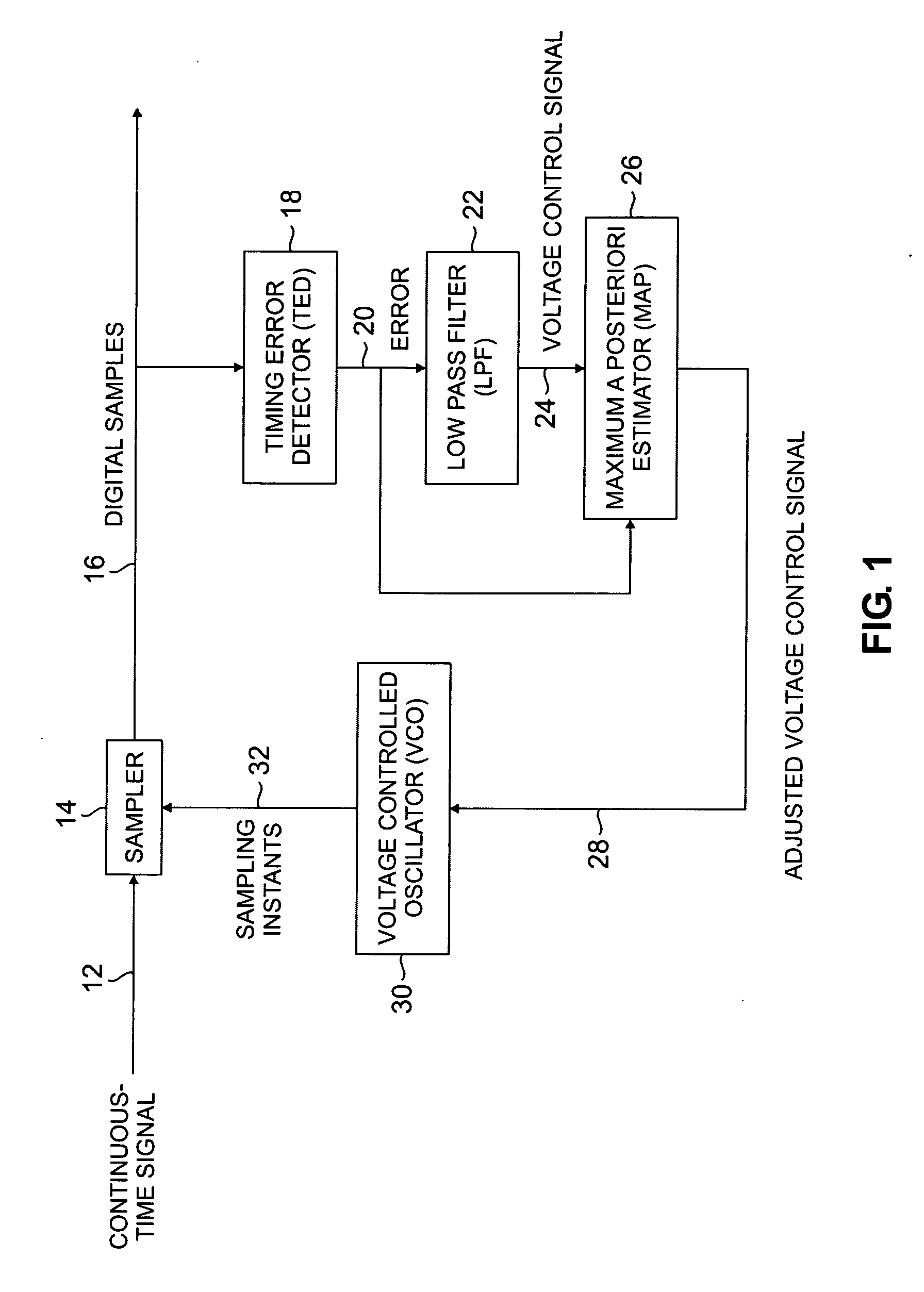
[0011]FIG. 1 shows an exemplary implementation of the present invention. Continuous time signal 12 is sampled by sampler 14, resulting in digital samples 16. Timing error detector (TED) 18 (sometimes referred to as a phase error detector or phase error comparator) receives digital samples 16 as an input signal, compares them to a reference signal, and generates error signal 20. Error signal 20 is operated on by low pass filter 22 to produce voltage control signal 24. The structure described thus far is part of a conventional PLL.

[0012] The present invention improves the conventional PLL by adding a statistical estimator, such as MAP estimator 26, to the circuit. The error represented by error signal 20 results from different sized gaps, also known as timing offsets, in digital samples 16. Digital data takes the form of a series of ones and zeros separated by spacing gaps. However, the size of every gap between the ones and zeros in a data stream is not the same. A PLL does not assu...


PUM


Abstract

A timing error recovery system includes a phase locked loop that receives a continuous time input signal, samples the input signal at a sampling rate and generates a voltage control signal. A statistical estimator, such as a maximum a posteriori estimator, compares the voltage control signal with an expected error based upon a statistical model and produces an adjusted voltage control signal that drives a voltage controlled oscillator to adjust the sampling rate.

Description

CROSS-REFERENCE TO RELATED APPLICATION(S) [0001] This application claims priority from Provisional Application 60 / 540,527, filed Jan. 30, 2004 entitled “Maximum a Posteriori (MAP) Timing Recovery” by A. Nayak and G. Feyh. INCORPORATION BY REFERENCE [0002] The aforementioned Provisional Application 60 / 540,527 is hereby incorporated by reference in its entirety.BACKGROUND OF THE INVENTION [0003] The invention relates generally to timing recovery in data storage systems. In particular, the present invention relates to using a maximum a posteriori (MAP) timing recovery estimator to determine and correct the error in a magnetic recording channel signal. [0004] Timing recovery is an important part of data storage systems. A common method of timing recovery is based on a phase-locked loop (PLL). Essentially, the PLL is a feedback loop that continually updates a sampling rate clock based on successive signal samples. This results in an error signal, which the PLL then uses to correct the sa...

Claims


Application Information

Patent Timeline
Patent Type & Authority Applications(United States)
IPC IPC(8): H04B17/00H04L7/02
CPCH04L7/0054
Inventor NAYAK, ARAVINDFEYH, GERMAN STEFAN OTTO
Owner AGERE SYST INC
Why Eureka
Try Eureka