Liquid crystal infiltrated optical fibre, method of its production, and use thereof

Inactive Publication Date: 2005-08-04
CRYSTAL FIBRE AS
View PDF3 Cites 111 Cited by
  • Summary
  • Abstract
  • Description
  • Claims
  • Application Information

AI Technical Summary

Benefits of technology

[0107] In a particular embodiment, the means for controlling the phase state of the liquid crystal material comprise a resulting electric field defining an angle with a longitudinal direction of the optical fibre that is different from 90°, such as a few degrees different, such as one or 2 degrees different. Thereby the formation of defects formed by reverse tilt domains in the liquid crystal material can be minimized or avoid

Problems solved by technology

It is a disadvantage of the disclosed fibres that the optical properties are not tuneable.
It is a disadvantage of the disclosed fibres that the optical properties are not tuneable without the use of relatively high temperature variations.
It is a further disadvantage that the optical properties are not optically or electrically tuneable and that no means for optical or electrical tuning are disclosed.
It is a disadvantage of the disclosed fibres that the optical properties are not tuneable without the use of relatively high temperature variations.
It is a disadvantage that the disclosed fibres are not optimised for providing photonic bandgab effect.
It is a further disadvantage that the optical properties are not optically or electrically tuneable and that no means for optical or electrical tuning are disclosed.
It is a dis

Method used


Image

  • Liquid crystal infiltrated optical fibre, method of its production, and use thereof
  • Liquid crystal infiltrated optical fibre, method of its production, and use thereof
  • Liquid crystal infiltrated optical fibre, method of its production, and use thereof

Examples


Embodiment Construction

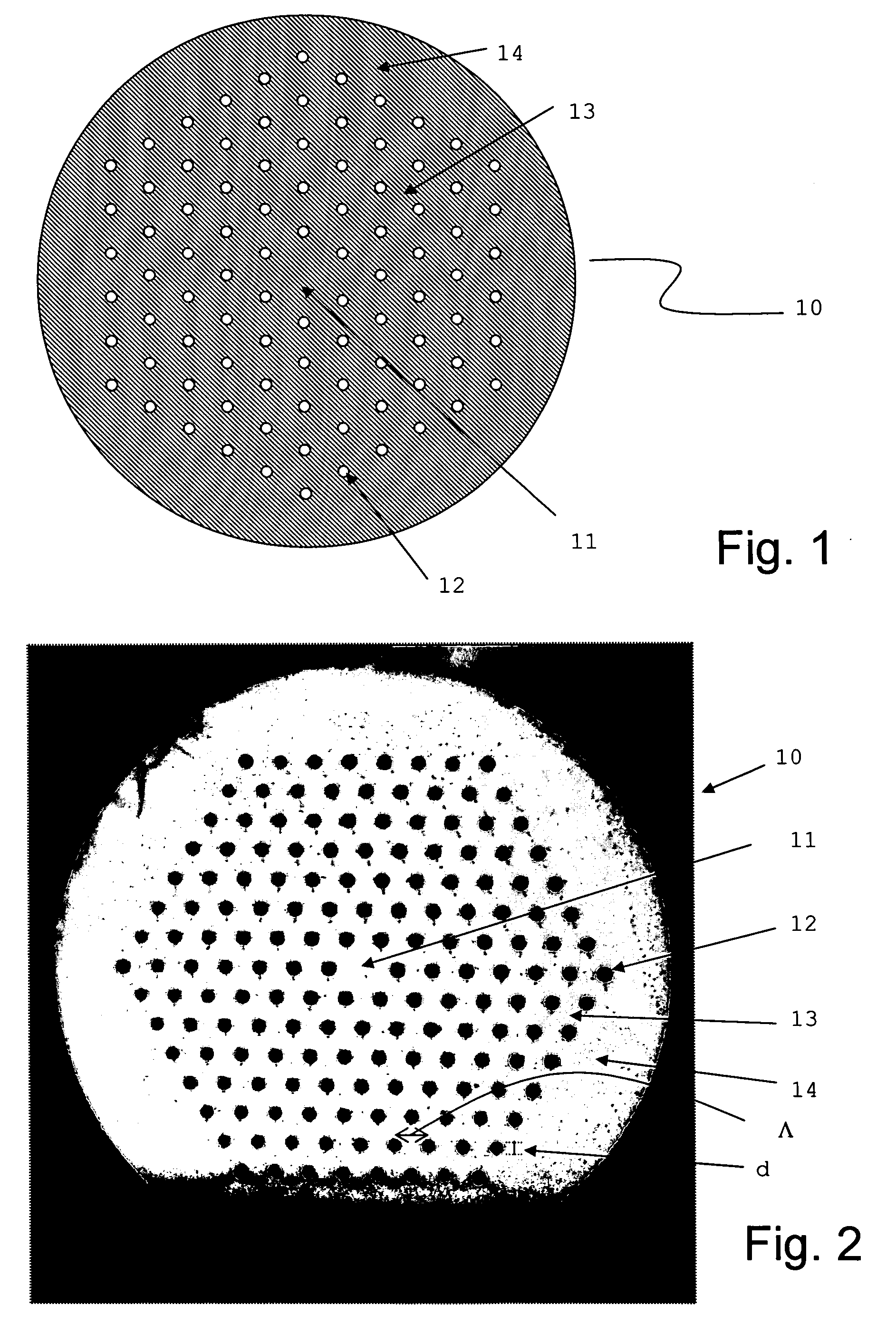
[0154]FIG. 1 schematically depicts the cross-section of an exemplary preferred embodiment of an optical fibre 10 according to the present invention. The optical fibre comprises a core region 11, a micro-structured cladding region surrounding said core region and comprising micro-structured cladding elements 12, or so-called cladding elements 12, at least a part of the cladding elements being filled with liquid crystal material(s). The cladding elements are here of equal size d, but variations may occur due to design and / or production variations. The cladding elements are placed in a background cladding material 13, and an over-cladding region 14.

[0155] In this example, the cladding elements surround the core region and define a substantially two-dimensional periodic lattice in the cross-section of the fibre. In the longitudinal direction of the fibre, at least a section of the optical fibre comprises cladding elements that are filled with liquid crystals. The liquid crystals may be...


PUM


Abstract

An optical fiber having a longitudinal direction and a cross-section perpendicular thereto, the optical fiber includes a core region; and a micro-structured cladding region, the cladding region surrounding the core region and having longitudinally extending micro-structure cladding elements arranged in a background cladding material, the micro-structured cladding elements having cross-sectional sizes which are equal or different, at least a number of the cladding elements being arranged in a substantially two dimensional periodic manner or a Bragg-type of manner, such as concentric rings of cladding elements surrounding the core, and the at least a number of the cladding elements are filled in at least one longitudinally extending section of the optical fiber with a liquid crystal material. The at least one filled section exhibits a photonic bandgap effect for at least one phase state of the liquid crystal.

Description

CROSS-REFERENCE TO RELATED APPLICATIONS [0001] The present application claims the benefit of Danish Patent Application No. PA 2003-01953 filed in Denmark on Dec. 31, 2003, and U.S. Provisional Application No. 60 / 536,718, filed in the United States on Jan. 16, 2004, the entire contents of which are hereby incorporated herein by reference.BACKGROUND OF THE INVENTION [0002] The present invention relates to optical fibre wave guides with tuneable optical properties, and use thereof in various applications, such as optical switching, dispersion compensation, wavelength conversion, polarization control, polarization delay lines (birefringent elements) sensors, attenuators, filters, amplifiers, and lasers; in particular the invention relates to optical fibres and devices that have optical properties that are tuneable using optical, thermal and / or electrical control. THE TECHNICAL FIELD [0003] Optical fibres with tuneable optical properties are desired within a vast number of technical area...

Claims


Application Information

Patent Timeline
IPC IPC(8): G02B6/02G02F1/01G02F1/133
CPCG02B6/02347G02B6/02385G02F2202/32G02F1/01G02F1/132G02B6/0239G02F1/1326
Inventor ALKESKJOLD, THOMAS TANGGAARD
Owner CRYSTAL FIBRE AS
Why Eureka
Try Eureka