Scroll type fluid machinery

a fluid machinery and rotating technology, applied in the direction of machines/engines, rotary/oscillating piston pump components, liquid fuel engines, etc., can solve the problems of poor product quality, difficult reduction of compressor cost, and high temperature of the end plates of fixed scrolls and orbiting scrolls, so as to reduce the overall size of the machine, and achieve high cooling performan

Inactive Publication Date: 2005-08-04
HITACHI LTD
View PDF4 Cites 39 Cited by
  • Summary
  • Abstract
  • Description
  • Claims
  • Application Information

AI Technical Summary

Benefits of technology

[0013] In view of the above-mentioned problems accompanying the prior art, the present invention has been made. It is an object of the present invention to provide a scroll type fluid machine which comprises a simple cooling structure, to thereby reduce an overall size of the machine while securing high cooling performance to sufficiently cool wide areas on axially opposite sides of the casing, and which is capable of suppressing noise and power consumption.

Problems solved by technology

In this case, the respective end plates of the fixed scrolls and the orbiting scrolls are subject to high temperatures due to compression heat generated during a compression operation.
Further, due to attachment of two electric fans, a reduction in cost of the compressor is difficult.
Due to operation of the electric fans, the compressor generates pronounced noise and a large amount of heat, and power consumption increases, resulting in poor product quality.
Therefore, the structures of the casing and the fixed scrolls are complicated.
This complicates the structure of the orbiting scroll and requires cumbersome operations for machining and assembling the orbiting scroll, thus lowering productivity.

Method used


Image

  • Scroll type fluid machinery
  • Scroll type fluid machinery
  • Scroll type fluid machinery

Examples


first embodiment

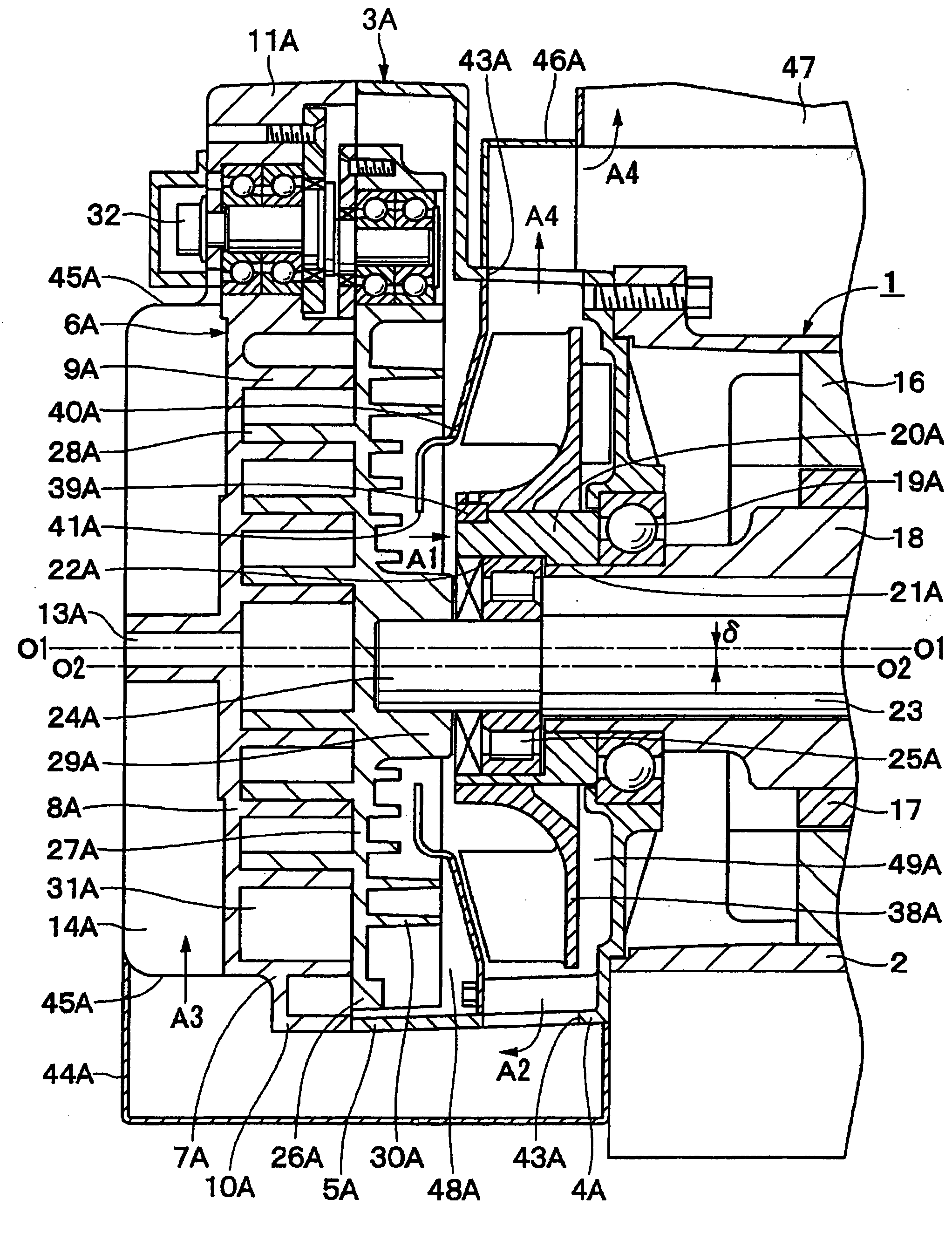
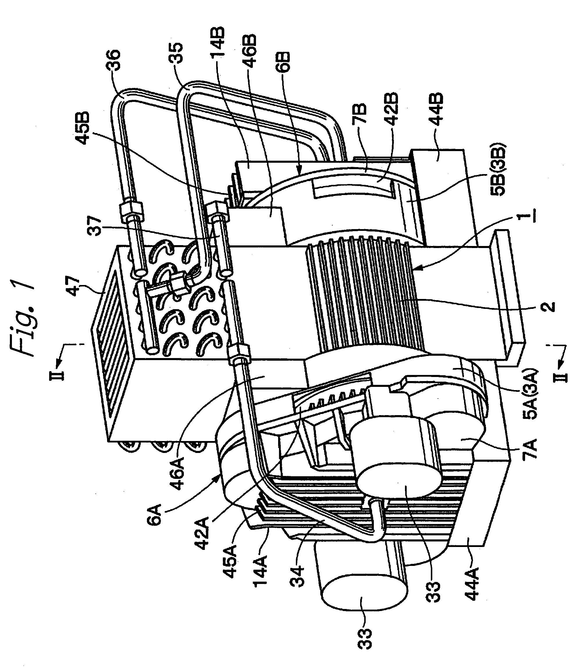
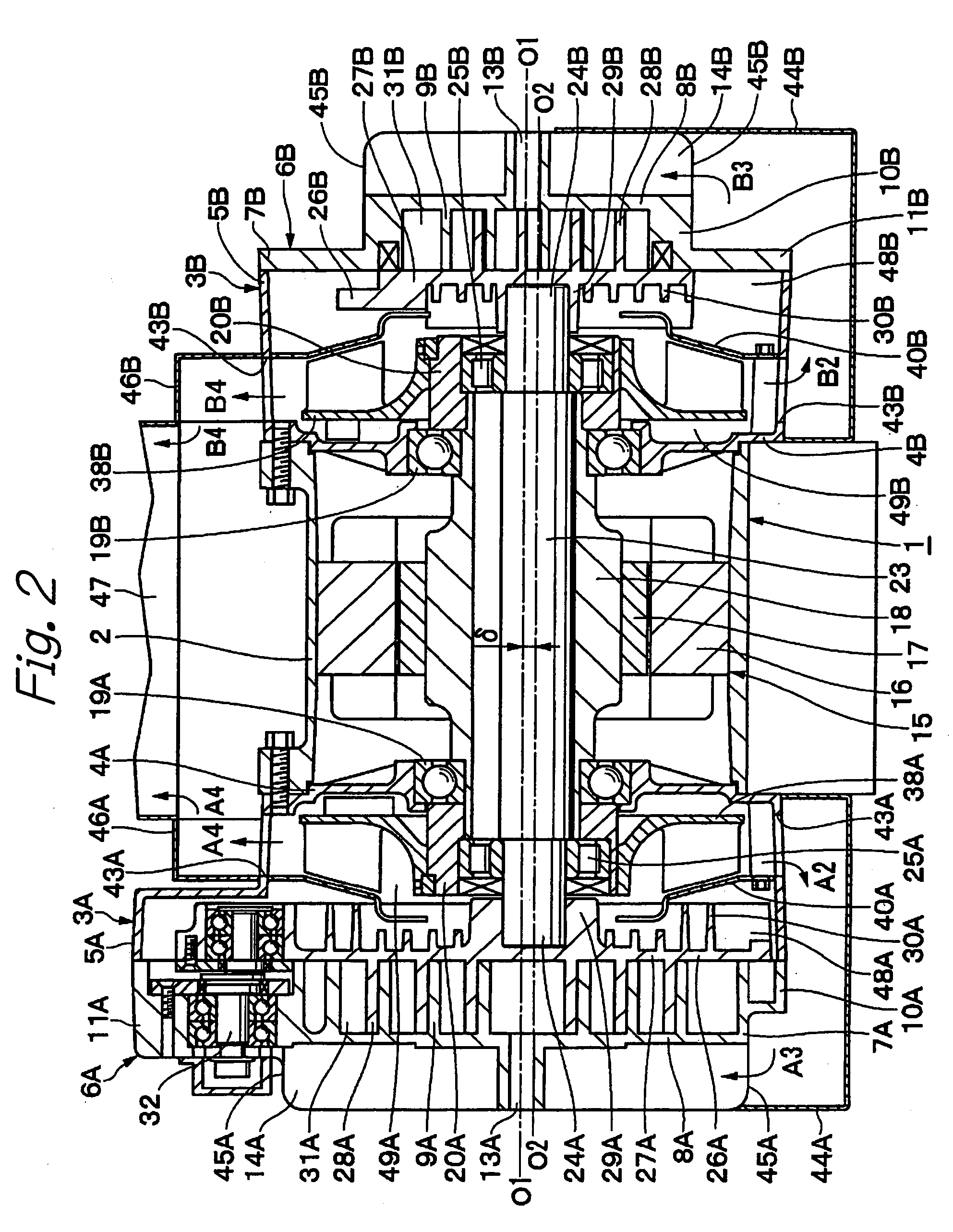
[0091] FIGS. 1 to 6 show the present invention. In this embodiment, a scroll type air compressor of a twin wrap type is taken as an example.

[0092] In the drawings, reference numeral 1 denotes a substantially cylindrical casing forming an outer frame of the scroll type air compressor. The casing 1, together with fixed scrolls 7A and 7B described later, forms a fixed-side member. As indicated in FIGS. 1 and 2, the casing 1 comprises an intermediate case 2 in a substantially cylindrical form, having a center axis O1-O1 and having axially opposing open ends (on a left side and a right side of the intermediate case in FIG. 2), and outer cases 3A and 3B attached to axially opposite ends of the intermediate case 2.

[0093] As shown in FIGS. 5 and 6, the first outer case 3A, which is located on one axial side (a left side in FIG. 2) of the intermediate case 2, is substantially in the form of a bottomed cylinder having axially opposing ends, one of which is open and the other of which is clos...

second embodiment

[0191] A twin type scroll air compressor in the second embodiment is arranged in the above-mentioned manner. Next, flow of cooling air is described.

[0192] In the low-pressure-stage compression portion 54A, as indicated by the arrows a1, a2, a3 and a4 in FIG. 9, cooling air flows along substantially the same passages as in the first embodiment. When the cooling fan 71A is operated, cooling air is sucked from the flow inlet openings 75A into the scroll / partition plate interspace 81 along the reverse side of the orbiting scroll 66A. Then, the cooling air flows from the motor / partition plate interspace 82 through the upper-side and lower-side flow outlet openings 76A into the ducts 77A and 80A, thus cooling the fixed scroll 55A and the cooling device 47.

[0193] On the other hand, in the high-pressure-stage compression portion 54B, as indicated by the arrows b1 in FIG. 10, cooling air is sucked from the flow inlet openings 75B into the motor / partition plate interspace 83 by operation of ...


PUM


Abstract

The present invention provides a scroll type fluid machine which enables both of a fixed scroll and an orbiting scroll to be cooled by means of a cooling fan, and which enables an overall size of the machine to be compact. Cooling fans 38A and 38B are connected to a rotary shaft 18 between an electric motor 15 and orbiting scrolls 26A and 26B. Outer cases 3A and 3B are provided with flow inlet openings 42A and 42B, flow outlet openings 43A and 43B, scroll ducts 44A and 44B and cooling device ducts 46A and 46B. Compression portions 6A and 6B are operated by rotatably driving the rotary shaft 18 using the electric motor 15. In this instance, the cooling fans 38A and 38B are rotated with the rotary shaft. Therefore, with a simple structure having no electric fans, the fixed scrolls 7A and 7B, the orbiting scrolls 26A and 26B and the cooling device 47 can be efficiently cooled, and a compressor having a compact size and a high cooling performance can be formed.

Description

BACKGROUND OF THE INVENTION [0001] The present invention relates to scroll type fluid machinery which can be suitably used, for example, for compressors for air or refrigerant, vacuum pumps, and the like. [0002] Generally, as an example of scroll type fluid machinery, there is known a scroll type air compressor in which orbiting scrolls are respectively provided on axially opposite sides of a rotary shaft. By driving the rotary shaft, compression of air or the like is conducted at axially opposite sides of the shaft (see, for example, Japanese Patent Application Public Disclosure No. 2002-13492). [0003] In a conventional air compressor of this type, first and second fixed scrolls are provided on axially opposite sides of a cylindrical casing. These fixed scrolls each comprise an end plate and a spiral wrap portion extending from a front surface of the end plate. [0004] In the casing, there are provided a rotary shaft comprising a cylindrical rod and an electric motor for rotatably d...

Claims


Application Information

Patent Timeline
Patent Type & Authority Applications(United States)
IPC IPC(8): F01C21/10F04C18/02F04C23/00F04C29/04
CPCF01C21/10F04C18/0215F04C29/04F04C23/001F04C18/0253
Inventor KOMAI, YUJIIKEDA, HIDEAKISUEFUJI, KAZUTAKAFUKUI, KOJISAKAMOTO, SUSUMUSUGIMOTO, MASANORI
Owner HITACHI LTD
Why Eureka
Try Eureka