Honeycomb filter for purifying exhaust gas

a technology of exhaust gas and honeycomb, which is applied in the direction of catalyst activation/preparation, metal/metal-oxide/metal-hydroxide catalyst, etc., can solve the problems of affecting the operation of the honeycomb filter, the failure of conventional honeycomb filters to sufficiently decompose and eliminate organic components, and the problem of exhaust gases discharged from the internal combustion engine of the vehicl

Inactive Publication Date: 2005-08-04
IBIDEN CO LTD
View PDF39 Cites 165 Cited by
  • Summary
  • Abstract
  • Description
  • Claims
  • Application Information

AI Technical Summary

Benefits of technology

[0017] The present invention is made to solve the above problems, and its object is to provide a honeycomb filter for purifying exhaust gases having a structure in that, even when comparatively large sealing material layer is included therein, there is hardly any increase in the amount of organic components contained in exhaust gases to be discharged.
[0018] According to a first aspect of the present invention, a honeycomb filter for purifying exhaust gases has a structure in which: a columnar body made of porous ceramic comprises a number of through holes, the above mentioned through holes being placed in parallel with one another in the length direction with wall portion interposed therebetween; a sealing material layer is formed on a circumference portion of the above mentioned columnar body; and the above mentioned wall portion which separates the above mentioned through holes functions as a filter for collecting particulates wherein a rate Sα of an area occupied by the sealing material layers to the total area of across-section including the through holes in the direction perpendicular to the through holes, in the above mentioned honeycomb filter for purifying exhaust gases, is set to 0.5% or more, and a rate Vα of organic components to the honeycomb filter for purifying exhaust gases is set to 0.5% by weight or less.
[0019] Moreover, according to a second aspect of the present invention, a honeycomb filter for purifying exhaust gases has a structure in which: a plurality of a columnar porous ceramic member are combined with one another through a sealing material layer to form a ceramic block, each of the above mentioned columnar porous ceramic member comprising a number of through holes, the above mentioned through holes being placed in parallel with one another in the length direction with partition wall interposed therebetween; a sealing material layer is formed on a circumference portion of the above mentioned ceramic block; and the above mentioned partition wall which separates the above mentioned through holes functions as a filter for collecting particulates, wherein a rate Sβ of an area occupied by the sealing material layers to the total area of a cross-section including the through holes in the direction perpendicular to the through holes, in the above mentioned honeycomb filter for purifying exhaust gases, is set to 2% or more, and a rate Vβ of organic components to the above mentioned honeycomb filter for purifying exhaust gases is set to 0.5% by weight or less.
[0020] In the following description, the honeycomb filter for purifying exhaust gases according to the first aspect of the present invention is simply referred to as the honeycomb filter according to the first aspect of the present invention, and the honeycomb filter for purifying exhaust gases according to the second aspect of the present invention is simply referred to as the honeycomb filter according to the second aspect of the present invention. When the two are not particularly distinguished, each of these is also simply referred to as the honeycomb filter of the present invention.

Problems solved by technology

In recent years, particulates contained in exhaust gases that are discharged from internal combustion engines of vehicles, such as buses, trucks and the like, and construction machines have raised serious problems since those particulates are harmful to the environment and the human body.
In this arrangement, however, since the sealing material layer of the conventional honeycomb filter contains a comparatively large amount of organic components, in the case of a honeycomb filter in which sealing material layers account for a great ratio, it contains a large amount of organic components.
However, conventional honeycomb filters have failed to sufficiently decompose and eliminate the organic components by using the above-mentioned catalyst.

Method used


Image

  • Honeycomb filter for purifying exhaust gas
  • Honeycomb filter for purifying exhaust gas
  • Honeycomb filter for purifying exhaust gas

Examples


example 1

[0159] (1) Talc having an average particle size of 10 μm (40 parts by weight), kaolin having an average particle size of 9 μm (10 parts by weight), alumina having an average particle size of 9.5 μm (17 parts by weight), aluminum hydroxide having an average particle size of 5 μm (16 parts by weight), silica having an average particle size of 10 μm (15 parts by weight) and a molding auxiliary (ethylene glycol) (6 parts by weight) were added to 16 parts by weight of water, and mixed and kneaded to prepare a material paste.

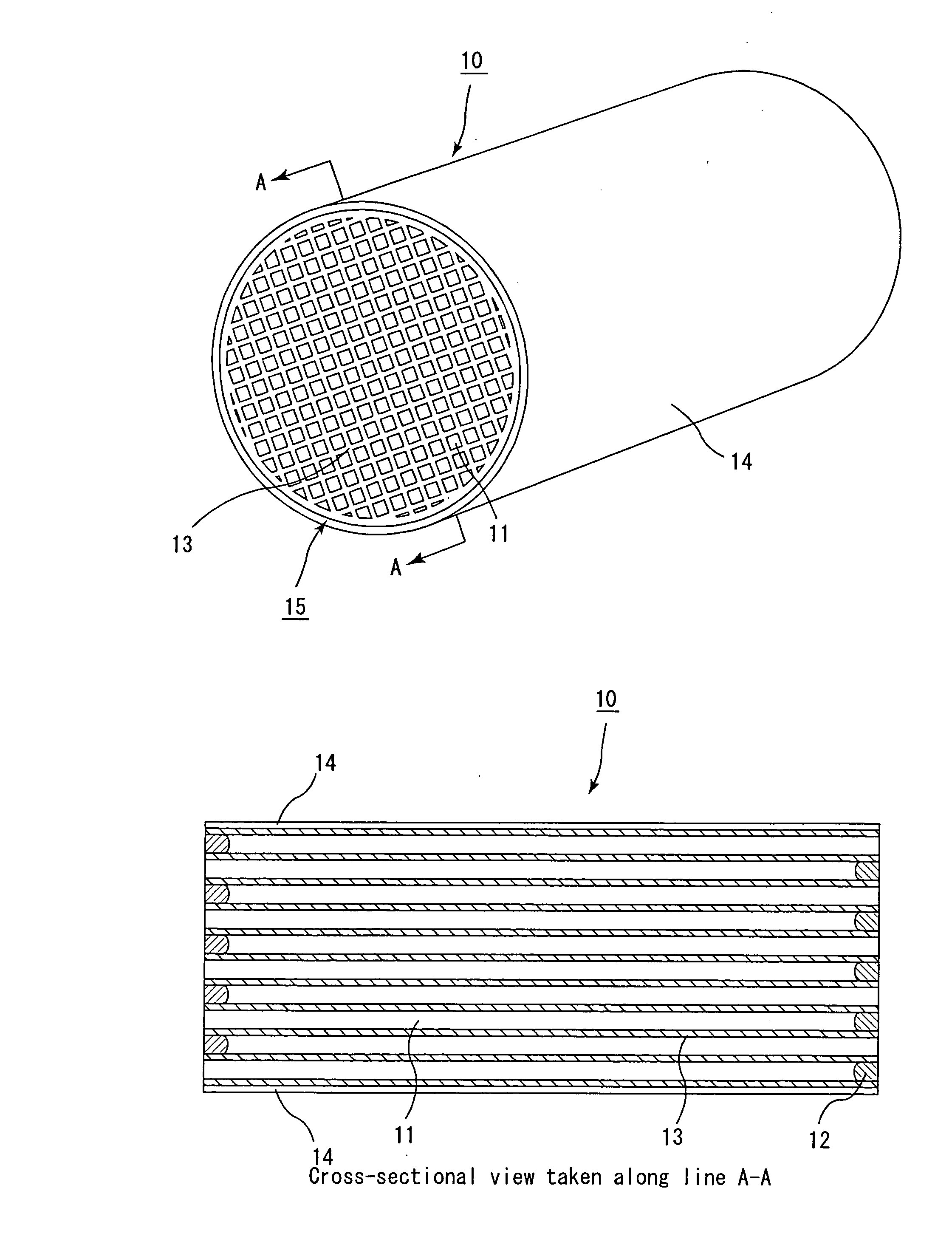
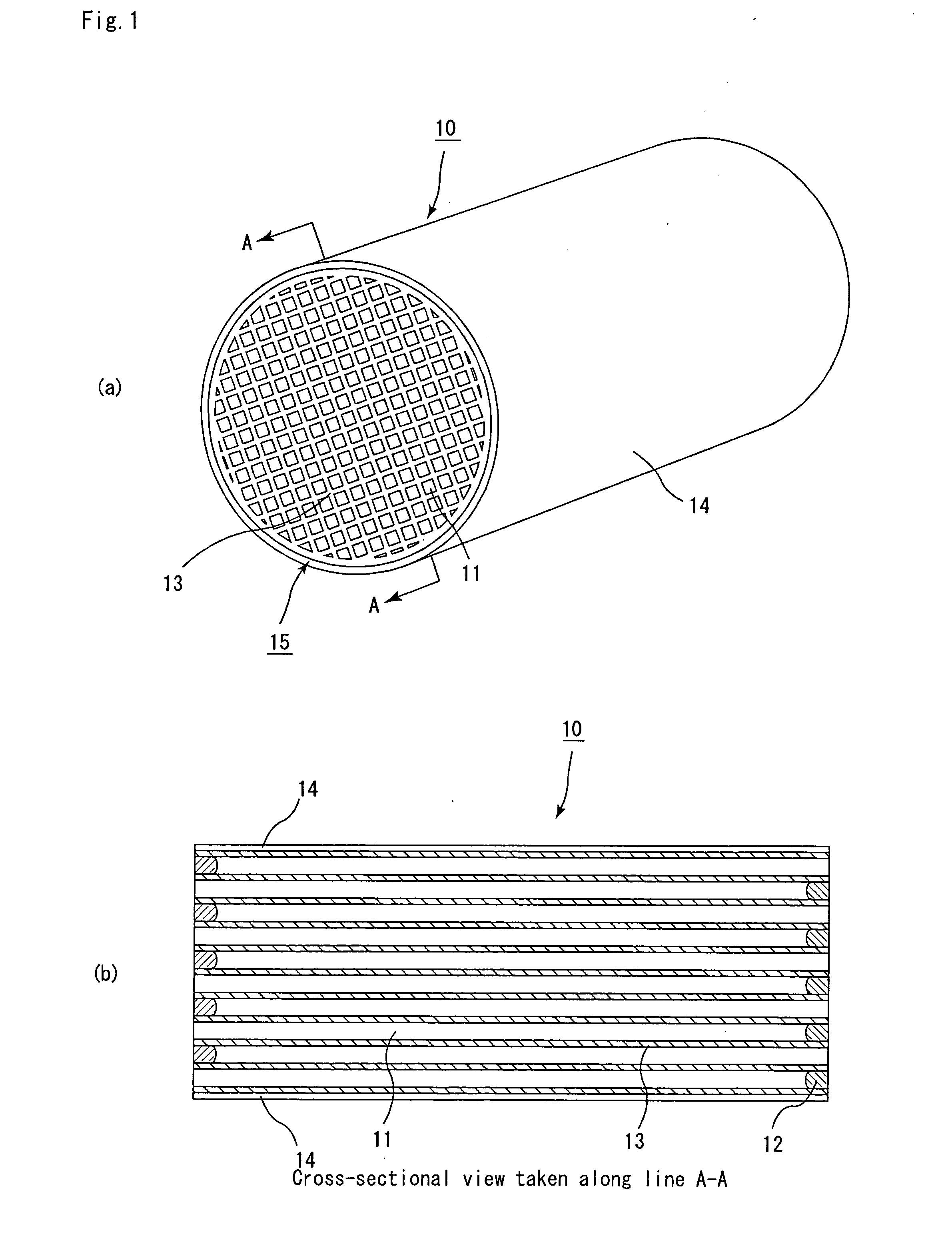
[0160] Next, the above-mentioned material paste was loaded into an extruder, and extruded at an extrusion rate of 10 cm / min so that a ceramic formed body having almost the same shape as the honeycomb filter 10 shown in FIG. 1 was formed, and the ceramic formed body was dried by a microwave drier, and predetermined through holes were then filled with a paste having the same composition as the material paste, and after this had been again dried by using a drier, this w...

example 2

[0165] First, the same processes as those of (1) and (2) of Example 1 were carried out to produce a honeycomb structural body.

[0166] Then, the above-mentioned honeycomb structural body was heated at 600° C. in an oxygen atmosphere for 60 minutes so that a honeycomb filter having a structure in that the rate Sα of the area occupied by the sealing material layers to the total area of a cross-section including the through holes in the direction perpendicular to the through holes was 1.4%, with the rate Vα of organic components being set to 0.10% by weight, was manufactured.

example 3

[0167] First, the same processes as those of (1) and (2) of Example 1 were carried out to produce a honeycomb structural body.

[0168] Then, the above-mentioned honeycomb structural body was heated at 500° C. in an oxygen atmosphere for 30 minutes so that a honeycomb filter having a structure in that the rate Sα of the area occupied by the sealing material layers to the total area of a cross-section including the through holes in the direction perpendicular to the through holes was 1.4%, with the rate Vα of organic components being set to 0.20% by weight, was manufactured.


PUM

PropertyMeasurementUnit
lengthaaaaaaaaaa
lengthaaaaaaaaaa
lengthaaaaaaaaaa

Abstract

An object of the present invention is to provide a honeycomb filter for purifying exhaust gases having a structure in that, even when comparatively large sealing material layer is included therein, there is hardly any increase in the amount of organic components contained in exhaust gases to be discharged. The present invention provides a honeycomb filter for purifying exhaust gases, having a structure in that a sealing material layer is formed on a circumference of a columnar body made of porous ceramics, which has a number of through holes placed in parallel with one another in the length direction with wall portion interposed therebetween, and the wall portion which separate the through holes from each other functions as a filter for collecting particulates, wherein the rate Sα of an area occupied by the sealing material layers to the total area of a cross-section including the through holes in the direction perpendicular to the through holes is set to 0.5% or more, and the rate Vα of organic components to the honeycomb filter for purifying exhaust gases is set to 0.5% by weight or less.

Description

CROSS REFERENCE TO RELATED APPLICATION [0001] This application claims benefit of priority to Japanese Patent Application No. 2002-81237, filed on Mar. 22, 2002, the contents of which are incorporated by reference herein. TECHNICAL FIELD [0002] The present invention relates to a honeycomb filter for purifying exhaust gases that is used as a filter for removing particulates and the like contained in exhaust gases discharged from an internal combustion engine such as a diesel engine or the like. BACKGROUND ART [0003] In recent years, particulates contained in exhaust gases that are discharged from internal combustion engines of vehicles, such as buses, trucks and the like, and construction machines have raised serious problems since those particulates are harmful to the environment and the human body. [0004] For this reason, there have been proposed various ceramic filters that allow exhaust gases to pass through porous ceramics and collect particulates in the exhaust gases to purify t...

Claims


Application Information

Patent Timeline
Patent Type & Authority Applications(United States)
IPC IPC(8): B01D46/24B01D53/94B01J23/42B01J35/04B01J37/00B01J37/02C04B35/195C04B35/636C04B35/80C04B38/00F01N3/022F01N3/035
CPCB01D46/2451B01D46/2455F01N2330/06F01N3/035F01N3/0222B01D46/2459B01D46/2462B01D46/2466B01D53/94B01D2046/2496B01J23/42B01J35/04B01J37/0009B01J37/0242C04B35/195C04B35/565C04B35/62655C04B35/6316C04B35/6365C04B35/806C04B38/0006C04B2111/00017C04B2111/00793C04B2235/3217C04B2235/3218C04B2235/3418C04B2235/3445C04B2235/349C04B2235/3826C04B2235/383C04B2235/3834C04B2235/428C04B2235/5224C04B2235/526C04B2235/5436C04B2235/5445C04B2235/6021C04B2235/668C04B2235/80C04B2235/96C04B35/00C04B35/80B01D46/2498B01D46/2484B01D46/2476B01D46/2478
Inventor SHIBATA, TOSHIAKI
Owner IBIDEN CO LTD
Why Eureka
Try Eureka