
Mobile radio receiver device

Active Publication Date: 2005-08-04
APPLE INC
View PDF17 Cites 13 Cited by
  • Summary
  • Abstract
  • Description
  • Claims
  • Application Information

AI Technical Summary

Benefits of technology

[0018] Depending on whether the local oscillator signal or the useful signal itself is changed over or interchanged in terms of the I and Q signal components, the generated output signal from the down-conversion frequency mixer may also have a phase shift of 90° from the signal which is actually desired and / or an inverse arithmetic sign for the generated signal. This has no disadvantageous effects on the further signal processing in the receiver, however.
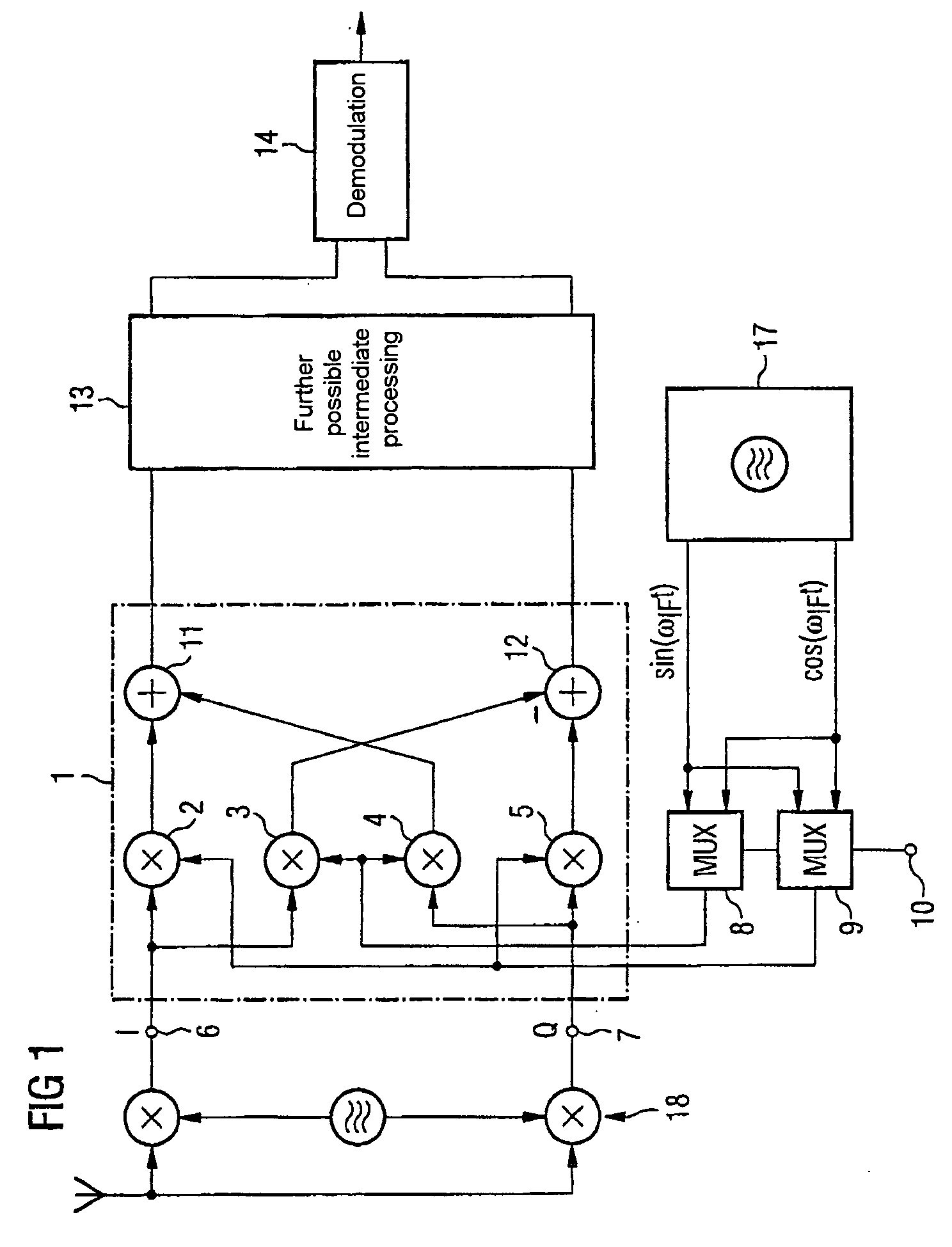
[0019] In line with one embodiment of the invention, the device for interchanging the in-phase and quadrature connections comprises a first multiplexer and a second multiplexer. The outputs of the two multiplexers are connected to the in-phase and quadrature connections of the first or second inputs of the down-conversion frequency mixer.
[0020] Accordingly, the device for interchanging the in-phase and quadrature connections with the two multiplexers interchanges the in-phase and quadrature components either of the useful signal or of the local oscillator signal at the input of the down-conversion frequency mixer.
[0021] The two multiplexers, in one example, each have a first and a second input which are connected to one another such that the outputs of the multiplexers provide the complex-value signal split into in-phase and quadrature components either in unchanged form or in a form with interchanged components, depending on a control signal. In this case, the control inputs are preferably connected to one another in order to supply the changeover control signal. The control signal is provided on the basis of whether the down-conversion frequency mixer's useful signal at the input is modulated in terms of its upper or in terms of its lower sideband.
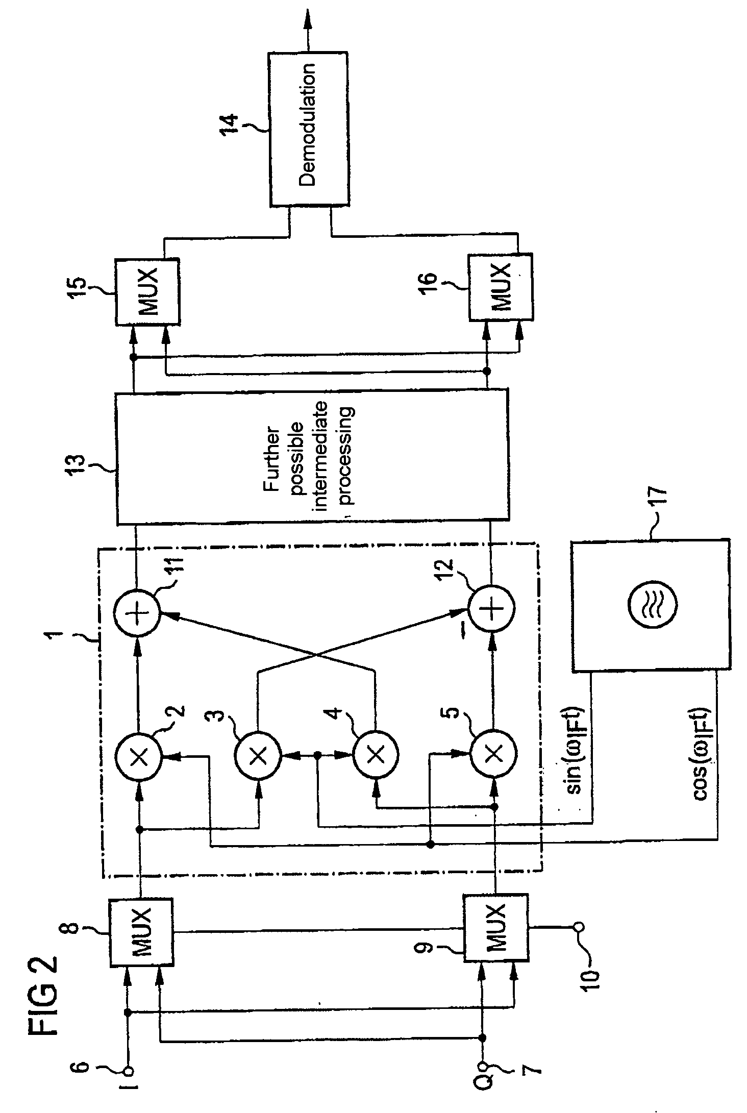
[0022] The receiver arrangement, in one example, comprises a heterodyne structure, for example a low-IF receiver structure. In this arrangement, besides the aforementioned down-conversion frequency mixer, which down-converts an intermediate-frequency signal to baseband in this case, a further down-conversion frequency mixer, which converts a radio-frequency signal to a complex-value intermediate-frequency signal, is connected upstream on the input side. The two down-conversion frequency mixers are preferably each supplied with a suitable local oscillator signal that may be generated by a respective phase locked loop, for example. In the case of a heterodyne receiver structure of this type, the device for changing over the in-phase and quadrature connections is accordingly connected either in the complex-value useful-signal path between the two down-conversion frequency mixers or between the frequency generator which generates the local oscillator signal and that down-conversion frequency mixer which brings about the conversion from intermediate-frequency level to baseband.
[0023] When the device for interchanging the in-phase and quadrature connections is connected between the two down-conversion frequency mixers, a further device for interchanging the in-phase and quadrature paths is advantageously connected to the output of the down-conversion frequency mixer that converts from intermediate frequency to baseband. This has the advantage that there is again compensation for an arithmetic sign caused as a result of interchanging the components of the useful signal.

Problems solved by technology

In transceivers designed in this manner between which there is a point-to-point connection, the problem regularly arises that the intermediate frequency differing from zero means that it is always necessary to change channels between the send and receive time slots.
However, this disadvantageously results in the net data transmission rate achieved using the transmission channel being greatly reduced from the gross data rate.
However, it remains a drawback of such receiver structures that the receivers need to be designed, in terms of the second down-conversion mixing stage, which down-converts from intermediate frequency to baseband, both for a situation in which the channel frequency is below the local oscillator frequency of the second mixing stage and for a situation in which the channel frequency is above the local oscillator frequency of the second mixing stage.
This naturally means increased additional complexity.

Method used


Image

  • Mobile radio receiver device
  • Mobile radio receiver device
  • Mobile radio receiver device

Examples


Embodiment Construction

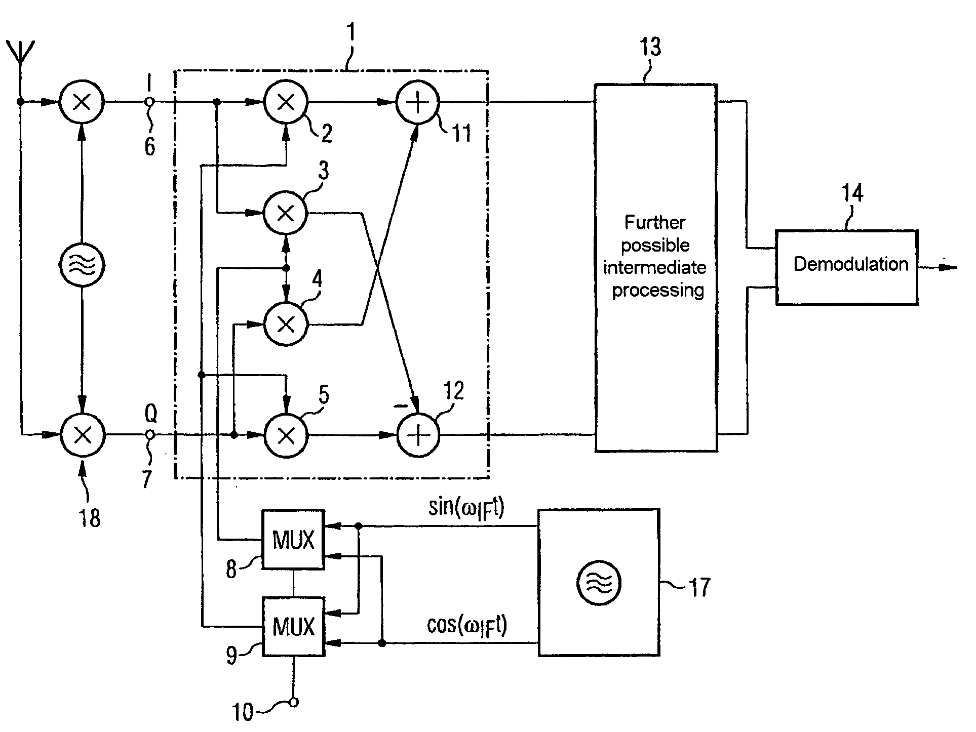
[0028]FIG. 1 shows a receiver arrangement with a down-conversion frequency mixer 1 which is designed to down-convert a useful signal, which is available as a complex-value signal, from an intermediate-frequency level to baseband. In this case, the complex-value signal is a signal that is split into an in-phase component and a quadrature component that is orthogonal thereto. Such frequency mixers 1 designed for complex-value signal processing are also called IQ mixers. The present down-conversion frequency mixer 1 comprises four mixer cells 2 to 5 which each have two inputs and one output, and which each provides a multiplied signal. The first input of the first mixer cell 2 is connected to the in-phase input 6 of the frequency mixer 1, as is the first input of the second mixer cell 3. The first inputs of the third and fourth mixer cells 4, 5 are connected to the quadrature input 7 of the down-conversion frequency mixer 1.

[0029] The second inputs of the mixer cells 2 to 5 are suppli...


PUM


Abstract

The invention is directed to a receiver arrangement, for example, in a mobile radio, which allows the use of slowly locking phase locked loops for a point-to-point connection between two transceivers, even in the case of a heterodyne receiver structure. The need to change channels between a transmission slot and a reception slot is avoided by virtue of a changeover device being provided for the purpose of interchanging the in-phase and quadrature components at the input side on a down-conversion frequency mixer. This advantageously allows either the upper sideband or the lower sideband of a useful signal to be down-converted without the need to change channel.

Description

REFERENCE TO RELATED APPLICATIONS [0001] This application is a continuation of PCT / DE03 / 02137, which was not published in English, which claims the benefit of the priority date of German Patent Application No. DE 102 28 757.0, filed on Jun. 27, 2002, the contents of which both are herein incorporated by reference in their entireties. FIELD OF THE INVENTION [0002] The present invention relates to a receiver arrangement, particularly for mobile radio. BACKGROUND OF THE INVENTION [0003] Normally, modern digital mobile radio systems are exclusively full-duplex systems. Full-duplex systems are distinguished in that it is possible to send and receive data simultaneously. Reference is also made to full-duplex systems in this context when sending and receiving are not performed simultaneously but changeover between the transmission directions takes place without being noticed by the subscriber. [0004] In principle, a distinction is drawn between two duplex methods. In the case of “frequency...

Claims


Application Information

Patent Timeline
IPC IPC(8): H03D7/00H03D3/00H03D7/16H03D7/18H04B1/06H04B1/26H04B1/28H04B1/30H04B1/40H04L27/06H04L27/233H04L27/38
CPCH03D3/007H03D7/166H04B1/28H04L27/3854H04B1/403H04L27/063H04L27/2332H04B1/302
Inventor HAMMES, MARKUSWAASEN, STEFAN VAN
Owner APPLE INC
Learn More