Expanding ligament graft fixation system and method

a ligament and fixation system technology, applied in the field of expanding ligament graft fixation system and method, can solve the problems of partial or permanent disability, excessive stress being applied to these tissues, and ligament fixation schemes not being entirely successful

Inactive Publication Date: 2005-08-04
ETHICON INC
View PDF8 Cites 201 Cited by
  • Summary
  • Abstract
  • Description
  • Claims
  • Application Information

AI Technical Summary

Benefits of technology

[0007] The present invention provides a ligament graft fixation system for fixing ligament graft material within a bone tunnel in a way that better approximates the natural fixation point of the ligamentary material that is being replaced. The system of the invention includes an expandable fixation member having a graft receiving eyelet disposed proximate its distal end, opposed bone engaging elements disposed about its periphery, and an expansion plug receiving opening defined in its proximal end. The system also includes an expansion plug having a diameter greater than the diameter of the expansion plug receiving opening so that forceable insertion of the expansion plug into the expansion plug receiving opening causes an expansion of the expandable fixation member to drive the opposed bone engaging elements apart so as to fix the bone engaging elements, as well as the graft material, in a bone tunnel. The fixation system of the invention allows for fixation at the proximal end of the fixation member, which can be placed proximate to the edge of the bone tunnel to fix the graft as close to the anatomically correct position as desired.
[0009] In still other embodiments, the graft receiving eyelet can be provided on a separate tip that includes a proximal expansion plug that can forceably mate with a distal plug receiving opening on the fixation member. In this embodiment, proximal and distal expansion slots can be provided, and in some cases, the proximal and distal expansion slots can encourage expansion in different directions. For example, one or more distal slots can be employed to encourage expansion in a direction that will drive the opposed bone engaging elements apart so as to fix the fixation member to bone, while the one or more proximal slots can encourage expansion in a direction that will urge the graft material into closer contact with the bone tunnel walls. In this embodiment, it may be desirable to size the plugs and plug receiving openings to allow the proximal plug to enter the distal plug receiving opening first upon compressing the system to forceably engage the plugs so that the graft material does not bunch up upon fixation. This specific embodiment provides still more proximal fixation which can be provided near the edge of a bone tunnel as desired.

Problems solved by technology

Such injuries usually result from excessive stress being applied on these tissues.
If, however, ligamentary material is completely detached from its associated bone(s) or is severed, partial or permanent disability may result.
Such ligament fixation schemes have not been entirely successful.
For example, rigid attachment using “traditional” attachment devices such as staples, sutures and screws often cannot be maintained even under normal tensile loads.
Also, the use of sharp screws to create a locking interference fit between a bone plug / block and a bone tunnel may be problematic.
For instance, there is always the possibility of damaging the ligament during insertion of the screw.
In addition, it may be difficult to maintain the desired tension on the graft material during insertion of the screw.
Because the graft structure is not, in such schemes, rigidly fixed within the bone tunnels, movement of the graft structure may disrupt the healing process.
Another potential problem may arise even where the graft material appears to be successfully fixed within the bone tunnel.
As noted above, movement tends to prevent healing and fixation of the soft tissue to bone, so where the windshield wiper effect occurs, the portion of the graft that moves when the patient uses the reconstructed joint may never heal completely in the region near the edge of the bone tunnel.
This potential problem defeats the goal of most surgeons which is to have the graft material fix as close as possible to its natural fixation point before being damaged by injury or disease.

Method used


Image

  • Expanding ligament graft fixation system and method
  • Expanding ligament graft fixation system and method
  • Expanding ligament graft fixation system and method

Examples


Embodiment Construction

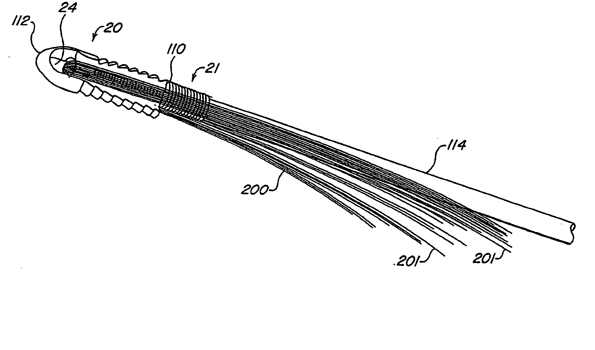
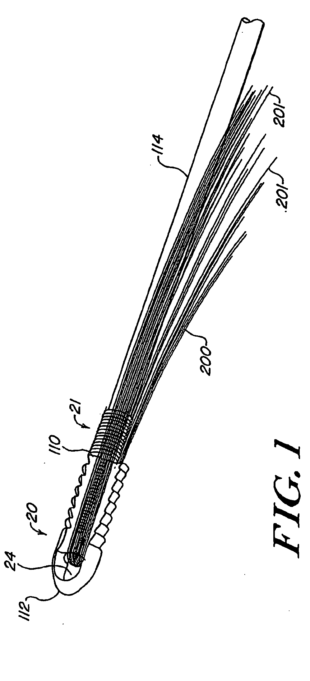
[0020] The present invention provides a device, system, and method useful for fixing soft tissue graft material within a bone tunnel to replace damaged ligamentary material and restore function to the portion of a patient's body in which the damaged ligamentary material was located. FIG. 1 provides an illustration of one such system of the invention having a fixation member 20, an expansion plug 21 positioned at a proximal end 110 of the fixation member, and a graft material holding element in the form of an eyelet 24 located proximate to a distal end 112 of the fixation member. Graft material 200 can be passed through eyelet 24 so that two ends 201 of the graft trail fixation member 20 proximally. An insertion element 114 mates with fixation member 20 and expansion plug 21 and extends proximally. In use, a surgeon inserts fixation member 20 along with graft material 200 into a prepared bone tunnel using insertion element 114 until the graft and fixation member are in the desired po...


PUM


Abstract

A graft fixation system for fixing graft material in a bone tunnel includes an expandable fixation member having a graft receiving eyelet disposed proximate its distal end, opposed bone engaging elements disposed about its periphery, and an expansion plug receiving opening defined in its proximal end. The system also includes an expansion plug having a diameter greater than the diameter of the expansion plug receiving opening so that forceable insertion of the expansion plug into the expansion plug receiving opening causes an expansion of the expandable fixation member driving the opposed bone engaging elements apart so as to fix the bone engaging elements, as well as the graft material, in a bone tunnel.

Description

FIELD OF THE INVENTION [0001] The present invention relates to systems and methods for locking and integrating soft tissue with bone. More specifically, systems and methods for use in conjunction with ligament replacement surgery are described. BACKGROUND OF THE INVENTION [0002] The complete or partial detachment of ligaments, tendons or other soft tissues (hereinafter “ligamentary material”) from the bones with which they are associated are commonplace, particularly among athletes. Such injuries usually result from excessive stress being applied on these tissues. Some degree of tissue detachment may occur, for instance, as the result of an accident, overexertion during a work-related activity, stress during the course of an athletic event, or in conjunction with numerous other situations and activities. If, however, ligamentary material is completely detached from its associated bone(s) or is severed, partial or permanent disability may result. [0003] Fortunately, there are numerou...

Claims


Application Information

Patent Timeline
Patent Type & Authority Applications(United States)
IPC IPC(8): A61F2/08A61B17/56
CPCA61F2/0805A61F2/0811A61F2002/0835A61F2002/0888A61F2002/0858A61F2002/0882A61F2002/0852
Inventor JUSTIN, DANIEL F.WENSTROM, RICHARD F. JR.LEVY, ANDREW S.
Owner ETHICON INC
Why Eureka
Try Eureka