Finite element simulation

a simulation and element technology, applied in the field offinite element simulation, can solve the problems of not performing stress computation for rigid object elements, exceeding predefined stress limit values, and providing no method that makes it possible, so as to improve the critical classification of finite elements

Active Publication Date: 2005-08-04
CHEMTRON RES
View PDF3 Cites 36 Cited by
  • Summary
  • Abstract
  • Description
  • Claims
  • Application Information

AI Technical Summary

Benefits of technology

[0018] An object of the present invention is to provide a finite element

Problems solved by technology

No stress computation is performed for a rigid object element because this is impossible due to its stiffness.
However, exceeding the predefined stress limiting value may also simply result from the fact that meshing of a model is inevitably an approximate model of the actual indust

Method used


Image

  • Finite element simulation
  • Finite element simulation
  • Finite element simulation

Examples


Embodiment Construction

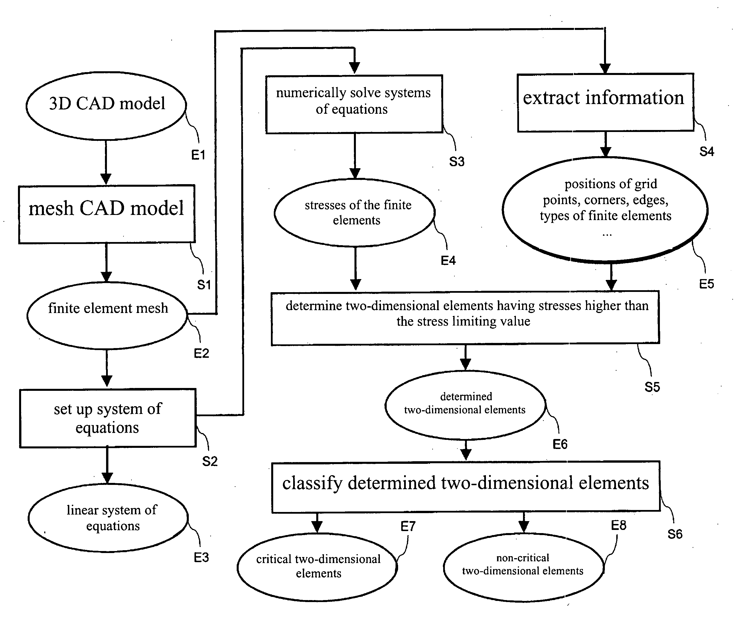
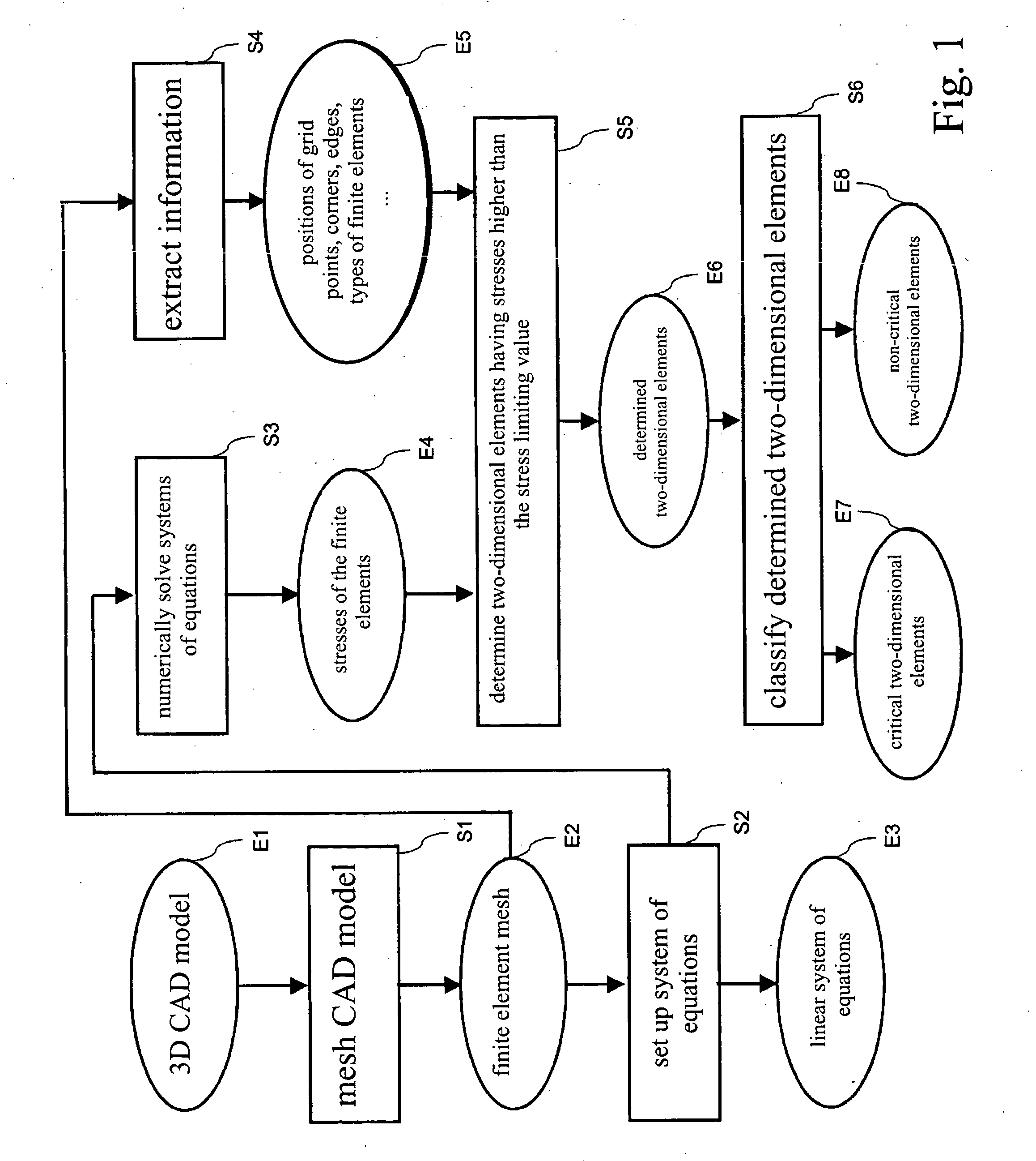
[0083] The exemplary embodiment refers to a three-dimensional CAD model of an automobile body. The CAD model functions in this example as a design model, and the body functions as an industrial system. The operational strength of a motor vehicle is predicted during product development by actual tests and also via simulations. In particular, it must be ensured that no damage such as cracks occur in the body during actual operation. Different design states are compared to one another via the tests and simulations in terms of the expected operational strength.

[0084] An electronic design model of the body or a partial system thereof to be studied, available to a computer, is generated and predefined for the method. In this example, the model has the form of a three-dimensional CAD model (result E1 in FIG. 1). It includes a plurality of component models for the body components. To generate the model, an operator preferably uses a tool for computer-aided design (CAD tool). A meshing tool...


PUM


Abstract

A method for automatic evaluation of a finite element simulation for an industrial system such as a motor vehicle body includes predefining an electronic design model of the industrial system and generating finite elements for the model. The stresses occurring in the finite elements are determined using a finite element simulation. Each finite element, which is a two-dimensional element and not a rigid object element and whose stress exceeds a predefined stress limiting value, is determined. For each determined two-dimensional element which is not a triangle, an element limiting value is determined on the basis of the stress limiting value. Each determined two-dimensional element is classified as critical if its computed stress exceeds the established element limiting value. The method enables identification of areas of the industrial system having a high stress and reduces the effect of inaccuracies that occur on the evaluation of the finite element simulation due to the approximation of the vehicle body by finite elements.

Description

[0001] Priority is claimed to German Patent Application No. DE 103 52 720.6, filed on Nov. 12, 2003, the entire disclosure of which is incorporated by reference herein. [0002] The present invention relates to a finite element simulation for an industrial system, for examples for an automobile body. BACKGROUND [0003] The finite element method is known from the “Dubbel—Taschenbuch für den Maschinenbau” [Dubbel's Handbook of Mechanical Engineering], 20th Ed., Springer Verlag, 2001, C48 through C50, from B. Klein: “FEM—Grundlagen und Anwendungen der Finite-Elemente-Methode” [FEM—Basic Principles and Applications of the Finite Element Method] Vieweg Verlag, 3rd Ed., 1999, from T. R. Chandrupalta and A. D. Belegundu: “Introduction to Finite Element in Engineering,” Prentice-Hall, 1991, and from DE 19927941 C1. Strength problems of all kinds, e.g., for stress distribution or stability, are solved numerically using a finite element simulation. For example, it is determined how a system made...

Claims


Application Information

Patent Timeline
IPC IPC(8): G06F17/10G06F17/50
CPCG06F17/5018Y02T10/82G06F2217/78G06F17/5095G06F30/15G06F30/23G06F2119/06
Inventor BREITFELD, THORSTENBUSCHBECK, FRANK
Owner CHEMTRON RES
Why Eureka
Try Eureka