Omni-Directional Thrust Vectoring Propulsor

Active Publication Date: 2016-08-04
ADAM MARTIN LEON
View PDF0 Cites 21 Cited by
  • Summary
  • Abstract
  • Description
  • Claims
  • Application Information

AI Technical Summary

Benefits of technology

[0036]Each independent swash plate system is in turn controlled by a user-operable active control system the function of which is to coordinate the magnitude and direction of the thrust forces generated by each rotor to achieve the desire sum for

Problems solved by technology

That is, at a reasonable cost in terms of the financial/economic costs, and also in terms of costs or detriments in relation to other aspects of aircraft performance.
There is therefore little or no possibility for retrofit or conversion to adapt existing helicopters to these configurations and the likelihood is that the resulting production aircraft will be high in cost.
Also at high speed, the drag from air re

Method used


Image

  • Omni-Directional Thrust Vectoring Propulsor
  • Omni-Directional Thrust Vectoring Propulsor
  • Omni-Directional Thrust Vectoring Propulsor

Examples


Embodiment Construction

[0078][Note: For ease of reference, an index of the reference numbers and symbols used in this Detailed Description section and the corresponding items / parts / assemblies shown in the Figures is included at the end of this Detailed Description section.]

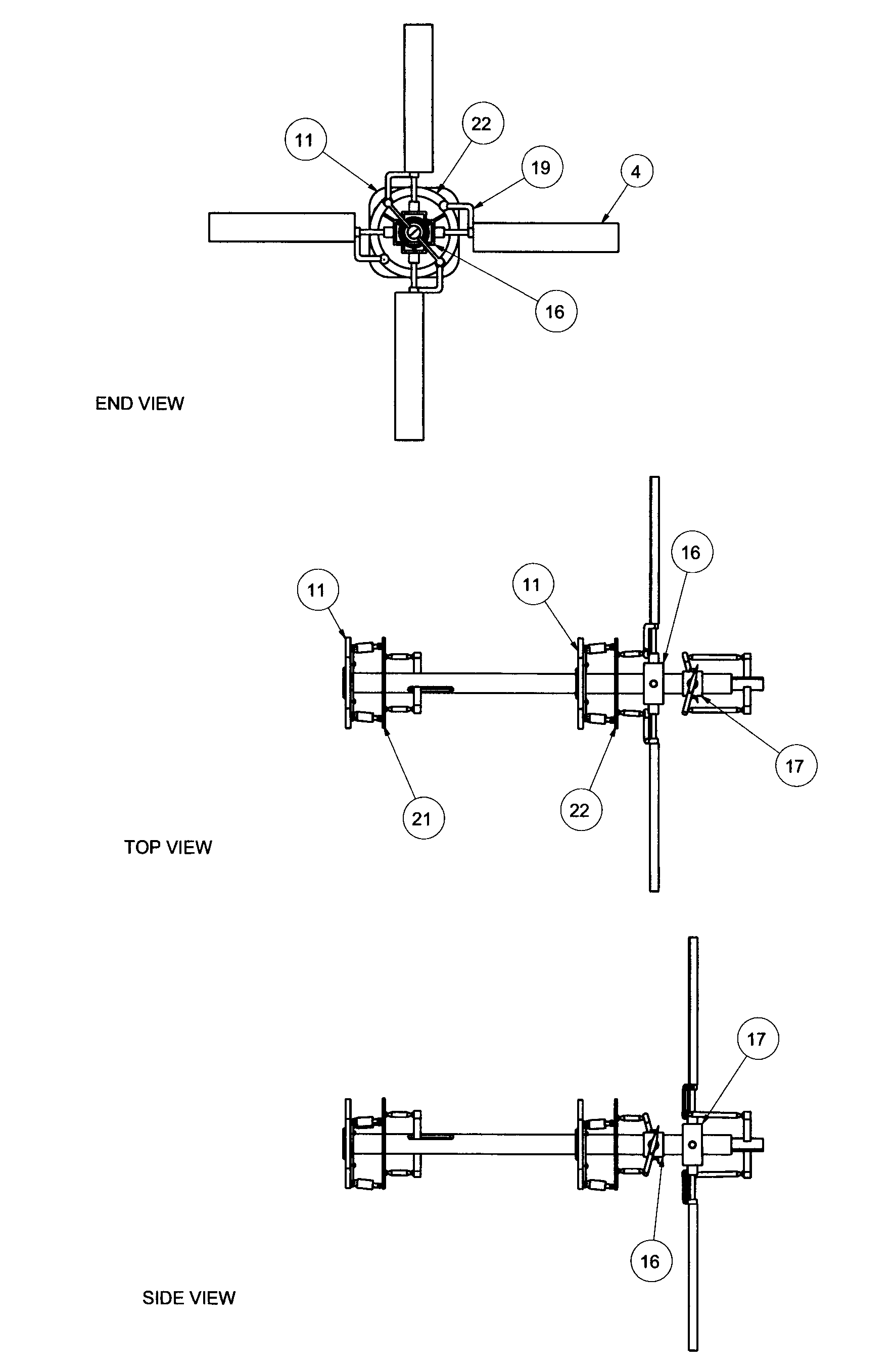
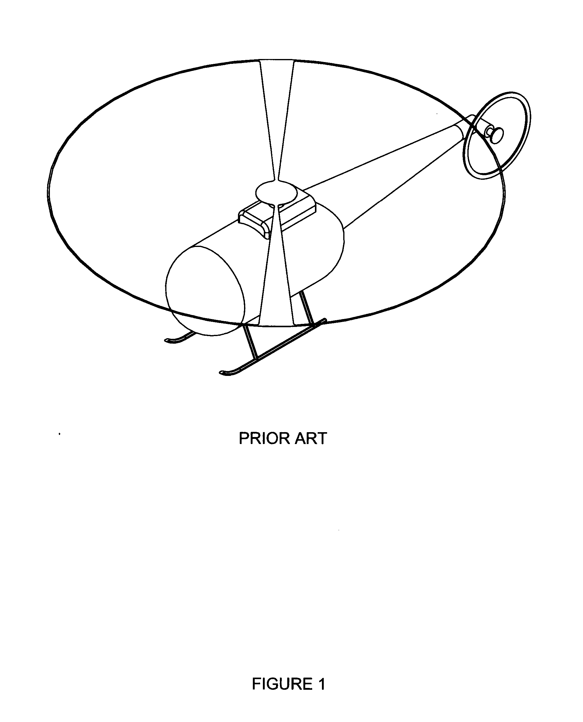
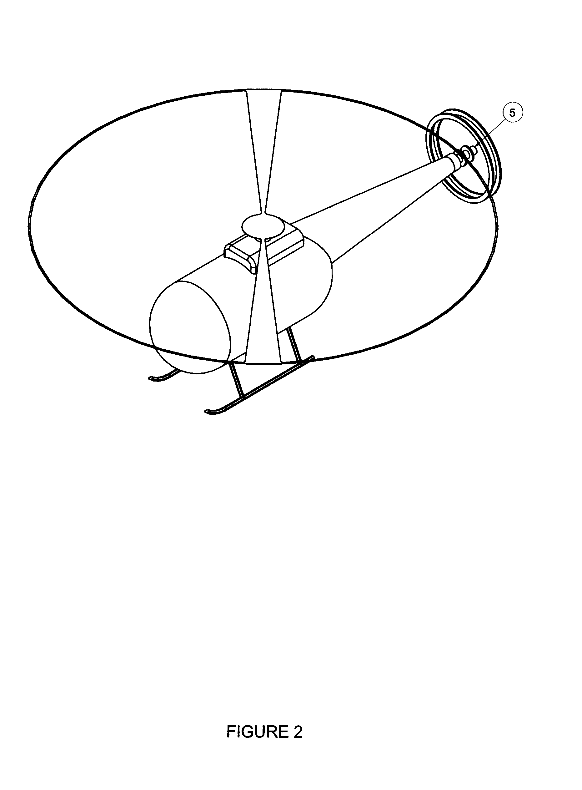
[0079]The particular embodiments of the invention illustrated in FIGS. 2-28 and described in further detail below relate to a propulsion system (referred to as an Omni-Directional Thrust Vectoring (ODTV) Propulsor or simply the Propulsor for short) for a helicopter or similar rotorcraft, which has the ability to produce a thrust force of a desired magnitude, in any desired radial direction from the centre of the Propulsor, from a single driveshaft that is fixed in position. However, whilst the particular embodiments shown in FIGS. 2-28 will be discussed in the context of helicopters and similar rotorcraft, it is to be clearly understood that (as noted above) no limitation whatsoever as to the scope or application of the invention is to ...


PUM


Abstract

A propulsion system comprising independent rotor sub-systems producing a thrust force of a desired magnitude in any desired radial direction from the centre of the propulsion system, driven from a single driveshaft that may be fixed in its position in the vehicle. When the propulsion system is fitted, for example, to a single-main-rotor helicopter in place of the convention anti-torque tail rotor, the helicopter is thereby equipped with a propulsion system that can produce yaw, pitch, the anti-torque lateral thrust for stability in hover, aft thrust or drag as well as the direct forward thrust that will enable the helicopter to fly at higher speeds. The propulsion system may also be applied in other aeronautical systems as well as to marine and industrial systems to impart energy into a fluid and thereby induce movement in that fluid.

Description

TECHNICAL FIELD[0001]The present invention will be explained (at least predominantly) in the context of helicopters and other similar types of aircraft / rotorcraft. Indeed, it is thought that embodiments of the invention may prove particularly advantageous for single-main-rotor type helicopters. However, no limitation whatsoever as to the scope or application of the invention is to be inferred from this, and the invention could potentially also be used in a wide range of other applications or industries. For instance, the invention might find use in other aeronautical applications such as, for example, in rotorcraft with other main rotor configurations, or in fixed-wing propeller driven aeroplanes, or stop-rotor type aircraft, or airships, etc. The invention might also find use in marine applications such as, for example, in ships, boats, submarines, etc. The invention may even find use in non-vehicle related industrial applications such as, for example, in stationary fans used to pr...

Claims


Application Information

Patent Timeline
IPC IPC(8): B64C27/82B64C27/605
CPCB64C27/82B64C2027/8218B64C2027/8227B64C27/605B64C2027/8236B64C27/52
Inventor ADAM, MARTIN LEON
Owner ADAM MARTIN LEON
Why Eureka
Try Eureka