Stator and resolving method and device thereof

Inactive Publication Date: 2005-08-11
MITSUBISHI ELECTRIC CORP
View PDF2 Cites 1 Cited by
  • Summary
  • Abstract
  • Description
  • Claims
  • Application Information

AI Technical Summary

Benefits of technology

[0010] This invention has been achieved to solve the above-mentioned problems, and it is an object of the invention to provide a stator in which a

Problems solved by technology

The method for resolving the stator as disclosed in JP-A-5-138453 had the problem that it took a longer time to resolve the stator, because the iron core projection forming the bottleneck opening of slot was deleted, and when the coil was treated with vanish, the resolving efficiency was lower, because the coil was not simply taken out of the iron core.
Also, the method for resolving the stator as disclosed in JP-A-11-75334 had the problem that the coil had a lower yield of

Method used


Image

  • Stator and resolving method and device thereof
  • Stator and resolving method and device thereof
  • Stator and resolving method and device thereof

Examples


Example

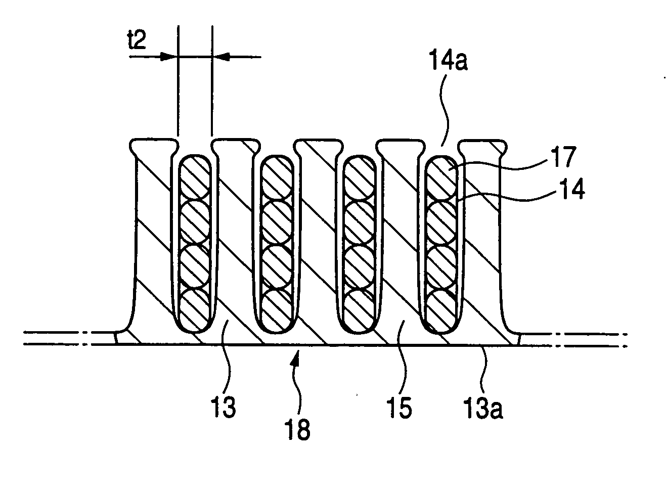
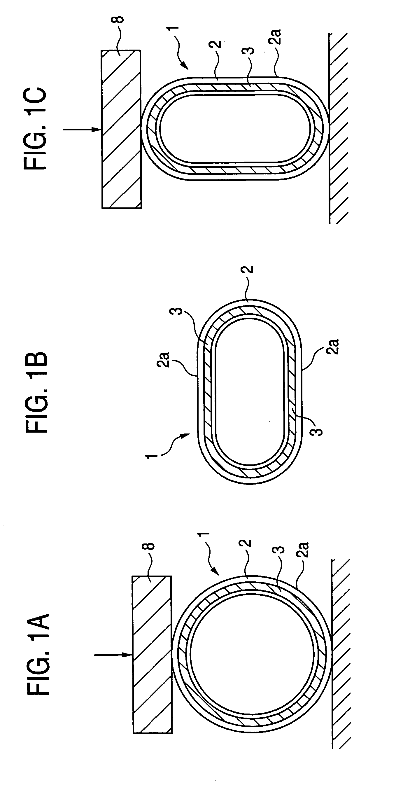
[0034] Referring to FIGS. 1A to 4, an embodiment 1 of this invention will be described below. The same or like parts are designated by the same numerals throughout the figures. FIG. 3 is a perspective view of a stator in an AC dynamo for vehicle, and FIG. 4 is a perspective view of an iron core. FIGS. 3 and 4 are the same views as FIGS. 6A and 8 disclosed in JP-A-9-103052. In FIGS. 3 and 4, a stator 1 has the iron core 2 and a coil 3, the iron core 2 being formed cylindrically by helically winding a band plate cut out from a strip steel plate. The iron core 2 has a plurality of slots 4 and teeth 5 around its inner circumferential face, each slot 4 having an opening portion 4a. A core back 6 of the iron core 2 has the concave portions 7 corresponding to the number and size of slots. The coil 3 of copper wire windings is inserted into the slots 4 of the iron core 2 through the opening portions 4a, and treated with vanish, whereby the stator 1 is built into the AC dynamo for vehicle.

[...

Example

Embodiment 2

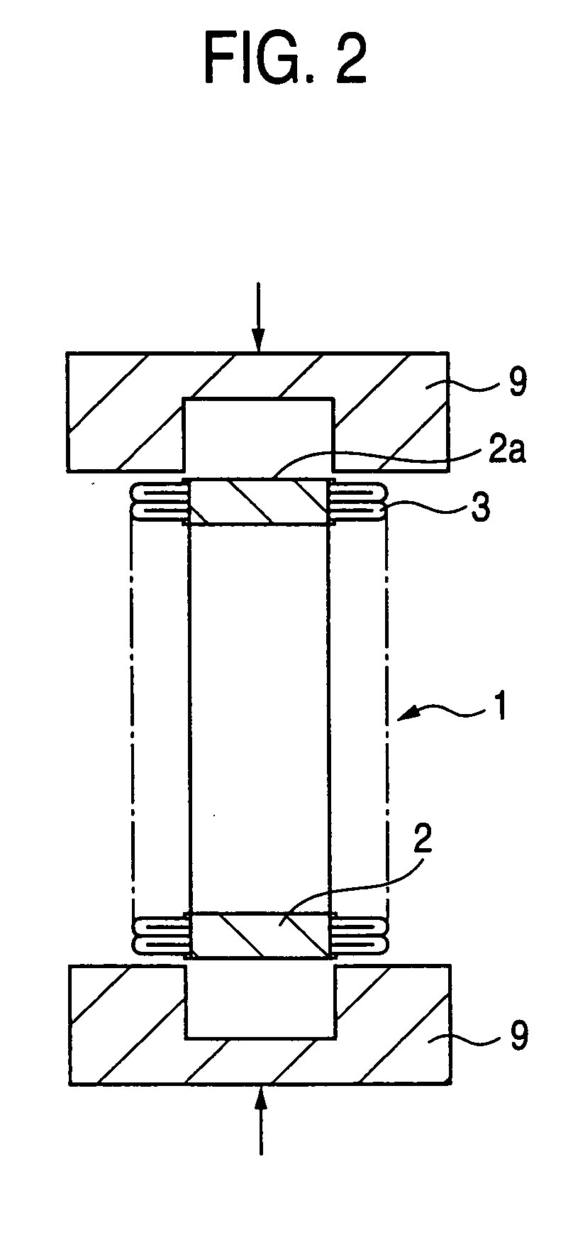
[0038] Referring to FIGS. 5A and 5B, an embodiment 2 of this invention will be described below. FIGS. 5A and 5B are explanatory views for explaining a step of enlarging the opening portion of slot and extracting the coil from the slot and means thereof. FIG. 5A is a front view, and FIG. 5B is a cross-sectional view taken along the line A-A in FIG. 5A. In FIGS. 5A and 5B, there are provided a pressing jig 10 for pressing the outer circumferential face 2a of the stator 1 toward the inner circumference, and a coil extracting jig 11 employed with the pressing jig 10 and capable of pressing separately from the pressing jig 10. Also, rotator for rotating the position of the stator 1 such as a motor is provided, whereby the stator 1 is rotated relative to the pressing jig 10 and the coil extracting jig 11, so that the coil is pressed multiple times. The coil extracting jig 11 has a shape of pressing the coil 3 on both end faces of the iron core 2 at the same time, whereby the ...

Example

Embodiment 3

[0041] Referring to FIGS. 6A and 6B, an embodiment 3 of this invention will be described below. FIGS. 6A and 6B are explanatory view for explaining a step of dividing the iron core in a circumferential direction and extracting the coil from the slot and means. FIG. 6A is an explanatory view showing the stator 1 divided along the line B-B, and FIG. 6B is an explanatory view for explaining how to extract the coil 3 from the divided stator 1. As shown in FIG. 6A, the stator 1 is divided into two pieces along the line B-B, employing dividing section such as a cutter. Moreover, the divided stator 1 is placed, and the coil 3 is pressed by a coil extracting jig 12 as extracting section for extracting the coil 3 and then extracted from the stator 1, as shown in FIG. 6B.

[0042] As above constituted, the rigidity of the stator 1 is decreased, because the stator 1 is divided, whereby the coil 3 is extracted under a smaller pressure. Also, since the stator 1 is divided, the coil 1 ...


PUM

PropertyMeasurementUnit
Timeaaaaaaaaaa
Shapeaaaaaaaaaa

Abstract

The method for resolving the stator having a coil disposed in the slots provided around an inner circumferential face of a cylindrical iron core and having an opening portion includes a step of enlarging the opening portion of the slot, and a step of extracting the coil from the slot.

Description

STATOR AND RESOLVING METHOD AND DEVICE THEREOF [0001] This is a divisional of application Ser. No. 10 / 635,611, filed Aug. 7, 2003. The above noted prior application is hereby incorporated by reference.BACKGROUND OF THE INVENTION [0002] 1. Field of the Invention [0003] The present invention relates to a stator, and a method and device for resolving the stator, in which the coil is easily resolved. [0004] 2. Description of the Related Art [0005] A conventional method for resolving the stator included deleting an iron core projection forming a bottleneck opening of slot in an iron core middle hole, pressing a coil end portion exposed out of the iron core at one end of the iron core toward the center of iron core around the entire circumference to extrude the coil side out of the slot into the iron core middle hole, reducing an apparent outer diameter of coil at the end portion of the coil under the iron core middle hole, and pressing the coil end portion in an axial center direction to...

Claims


Application Information

Patent Timeline
IPC IPC(8): H02K1/18H02K3/34H02K15/00H02K15/02
CPCH02K15/0006Y10T29/49009Y10T29/49011Y10T29/49073Y10T29/53274Y10T29/4902Y10T29/49012Y10T29/49822
Inventor ASAO, YOSHIHITOYAMAMOTO, KYOUHEI
Owner MITSUBISHI ELECTRIC CORP
Why Eureka
Try Eureka