Gas mixing apparatus

a technology of mixing apparatus and gas, which is applied in the direction of lighting and heating apparatus, combustion types, separation processes, etc., can solve the problem of short overall length of gas mixing apparatus, and achieve the effect of shortening the overall length of the apparatus

Inactive Publication Date: 2005-08-11
DENSO CORP
View PDF4 Cites 13 Cited by
  • Summary
  • Abstract
  • Description
  • Claims
  • Application Information

AI Technical Summary

Benefits of technology

[0006] In view of the above-described problems, the invention has an object to provide a gas mixing apparatus which includes a gas supplying device incorporated in an inner space of the gas mixing apparatus to shorten the length of the apparatus in the gas flowing direction.

Problems solved by technology

Thus, the overall length of the gas mixing apparatus is short.

Method used


Image

  • Gas mixing apparatus
  • Gas mixing apparatus
  • Gas mixing apparatus

Examples


first embodiment

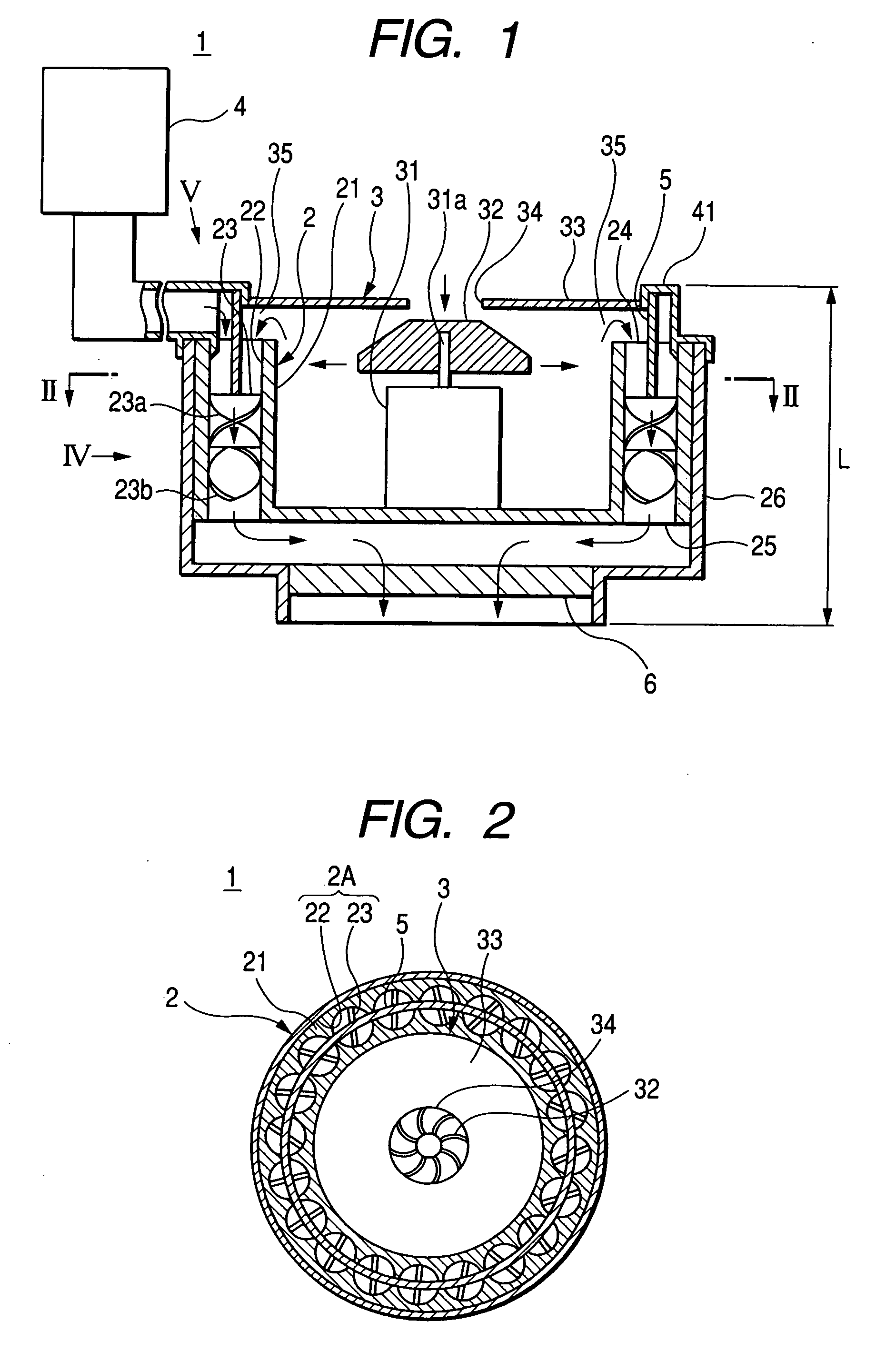
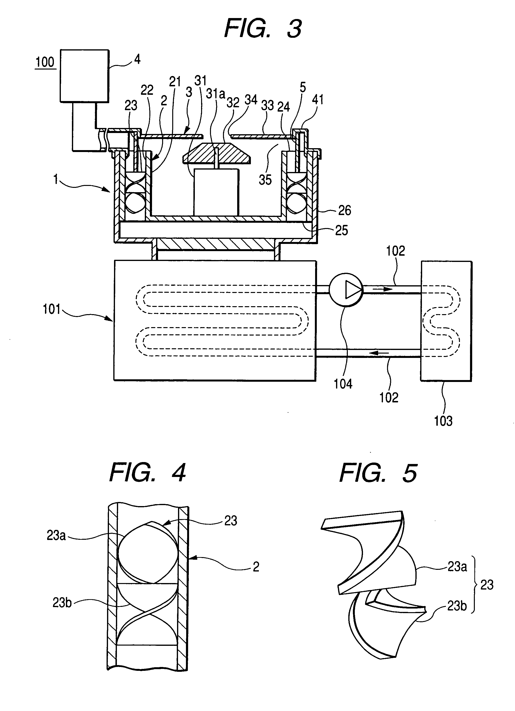
[0029]FIG. 1 is a cross-sectional view showing an overall arrangement of a fuel mixture generating apparatus 1 in accordance with a first embodiment of the present invention. FIG. 2 is a cross-sectional view of the fuel mixture generating apparatus 1 taken along a line II-II of FIG. 1. FIG. 3 is a partly cross-sectional view showing an arrangement of a catalytic combustion heater 100 incorporating the fuel mixture generating apparatus 1 in accordance with the first embodiment of the present invention. FIG. 4 is a cross-sectional side view showing a static mixer of the fuel mixture generating apparatus 1 seen from the direction IV of FIG. 1. FIG. 5 is a perspective view showing the arrangement of a fin 23 of the static mixer seen from the direction V of FIG. 1.

[0030] The catalytic combustion heater 100 is a device which causes the combustion of hydrogen gas. The generated heat is used in the air-conditioning apparatus. The catalytic combustion heater 100, as shown in FIG. 3, include...

second embodiment

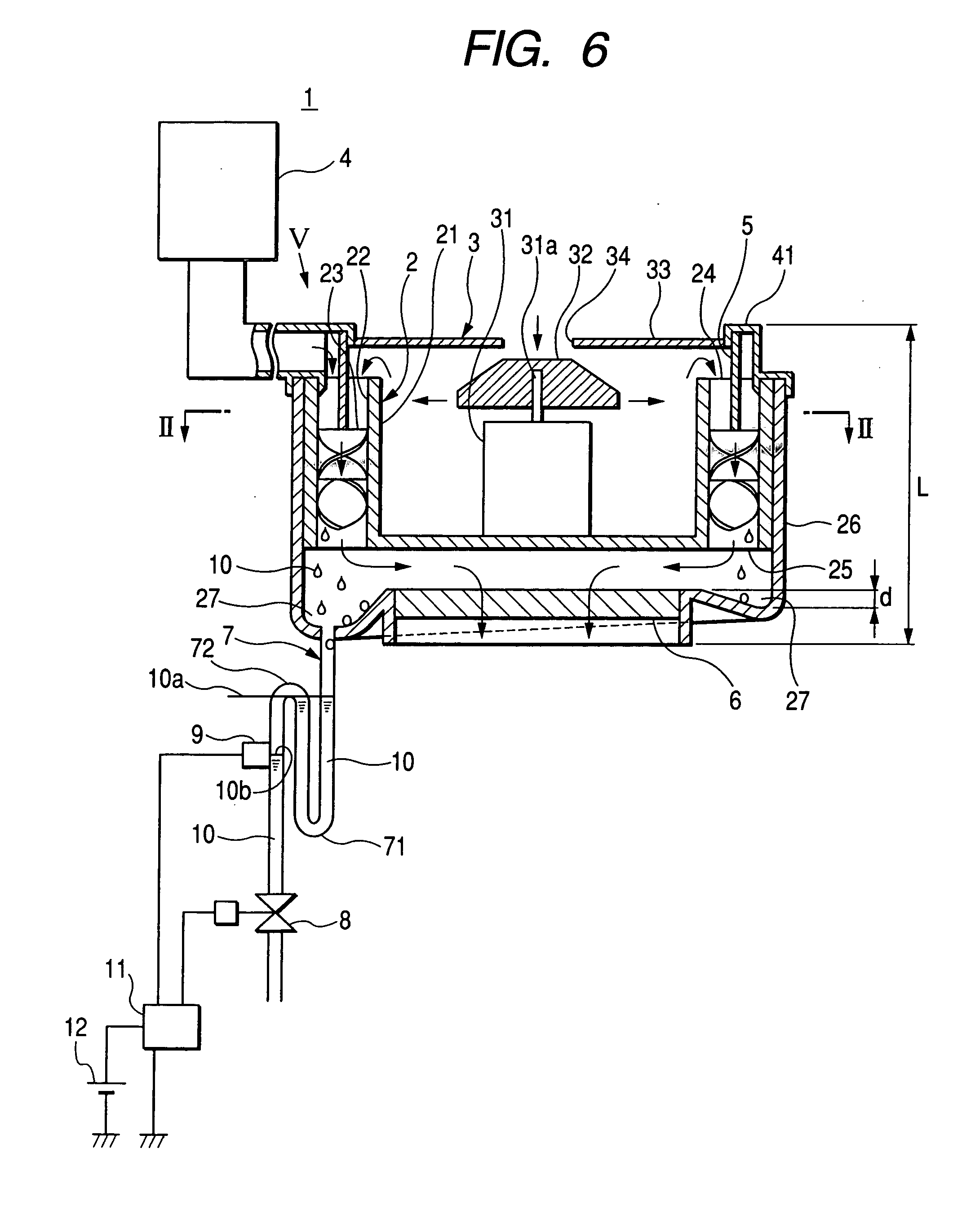
[0051]FIG. 6 is a cross-sectional view showing an overall arrangement of the fuel mixture generating apparatus 1 in accordance with a second embodiment of the present invention. FIG. 6 shows the used condition of the fuel mixture generating apparatus 1. The fuel mixture generating apparatus 1 in accordance with the second embodiment of the present invention is different from the fuel mixture generating apparatus 1 in accordance with the first embodiment of the present invention in the following points. First, the mixing element 2A in the static mixer 2 is characteristic in that the inner wall surface of the passage 22 and the surface of the fin 23 have water repellency. Second, the casing 26 of the static mixer 2 has a collection groove 27 provided in the vicinity of the outlet of the mixing element 2A. The collection groove 27 is a collecting means of the present invention. The collection groove 27 is connected to a drain pipe 7. The drain pipe 7, which is a draining means of the p...


PUM

PropertyMeasurementUnit
air-permeableaaaaaaaaaa
water repellentaaaaaaaaaa
diameteraaaaaaaaaa

Abstract

A static mixer includes a plurality of mixing elements disposed parallel to each other and arrayed annularly to define an inner cylindrical space surrounded by these mixing elements. Each mixing element has stationary vanes disposed in a circular passage. A blower supplying the air to the static mixer is entirely or partly accommodated and fixed in the inner cylindrical space of the static mixer. The static mixer and the blower are disposed parallel to each other. The overall length of the fuel mixture generating apparatus can be shortened.

Description

CROSS-REFERENCE TO RELATED APPLICATION [0001] This application is based upon and claims the benefit of priority from earlier Japanese Patent Application No. 2004-29708 filed on Feb. 5, 2004 and the Japanese Patent Application No. 2004-354636 filed on Dec. 7, 2004 so that the descriptions of which are incorporated herein by reference. BACKGROUND OF THE INVENTION [0002] The present invention relates to a gas mixing apparatus used for uniformly mixing two kinds of gases, and is preferably applicable to a fuel gas combustion apparatus which generates a fuel mixture of fuel gas and air. [0003] The Japanese Patent Application Laid-open No. 05-212259 (1993) discloses a static mixer including numerous rotary blades provided on the surfaces of two combined cones connected at their bottoms. This conventional static mixer provides numerous flow passages extending on the conical surfaces of two cones from one end (i.e. top of one cone) to the other end (i.e. top of the other cone), to produce a...

Claims


Application Information

Patent Timeline
Patent Type & Authority Applications(United States)
IPC IPC(8): B01D45/08F23K5/00B01F23/10F23D14/62
CPCB01F3/026F23D14/62F23C2900/9901B01F5/0615B01F23/19B01F25/43141
Inventor KIKAWA, SHUNJIRO
Owner DENSO CORP
Why Eureka
Try Eureka