Reduction gear and method and apparatus for manufacturing the reduction gear concerned, and electric power steering system with the reduction gear concerned

a technology of reduction gear and reduction gear, which is applied in the direction of heat treatment equipment, hoisting equipment, furnaces, etc., can solve the problems of large volume of carburizing hardening equipment, long processing time period, and surface roughness, and the need for finish grinding

Inactive Publication Date: 2005-08-11
NSK LTD +1
View PDF3 Cites 16 Cited by
  • Summary
  • Abstract
  • Description
  • Claims
  • Application Information

AI Technical Summary

Benefits of technology

[0012] Thus, it is an object of the present invention to provide a reduction gear capable of performing the inline processing within a short working time period, coping with small-sized treatment equipment while maintaining a predetermined hardness on the tooth surface, and after the treatment, grinding finish work, and a method of manufacturing the reduction gear concerned, and an electric power steering system provided with the reduction gear concerned.

Problems solved by technology

In the carburizing hardening treatment, however, there is a problem that deformation after the treatment is great and carburizing hardening equipment is large-sized and has also a long processing time period.
In the nitriding treatment, after the treatment, the surface becomes rough, and after the nitriding treatment, finish grinding becomes necessary.
Also, the nitriding treatment is batch treatment, and the incidental facilities are also apt to become equipment on a large scale, and further, there is a problem that the processing time period also becomes longer.
Also, although it is smaller than the carburizing hardening treatment, the deformation after the treatment has been also a problem.
Since high precision is demanded of the worm teeth of the electric power steering system, there is a problem that it is necessary in the plating treatment to control strictly.
Also, the plating treatment is batch treatment, and the incidental facilities are also apt to become equipment on a large scale, and further, there is a problem that the processing time period also becomes longer.
Also, any of the above-described carburizing hardening treatment, nitriding treatment and plating treatment is not suitable for inline processing, and for this reason, there is also a problem that there is no probability that the productivity will be improved.

Method used


Image

  • Reduction gear and method and apparatus for manufacturing the reduction gear concerned, and electric power steering system with the reduction gear concerned
  • Reduction gear and method and apparatus for manufacturing the reduction gear concerned, and electric power steering system with the reduction gear concerned
  • Reduction gear and method and apparatus for manufacturing the reduction gear concerned, and electric power steering system with the reduction gear concerned

Examples


Embodiment Construction

[0032] Hereinafter, with reference to the accompanying drawings, the detailed description will be made of an example of the present invention. In this respect, in these drawings, portions identical are designated by the identical reference numerals. Also, it goes without saying that the following examples explain the present invention exemplifically, and do not limit the present invention in any meaning.

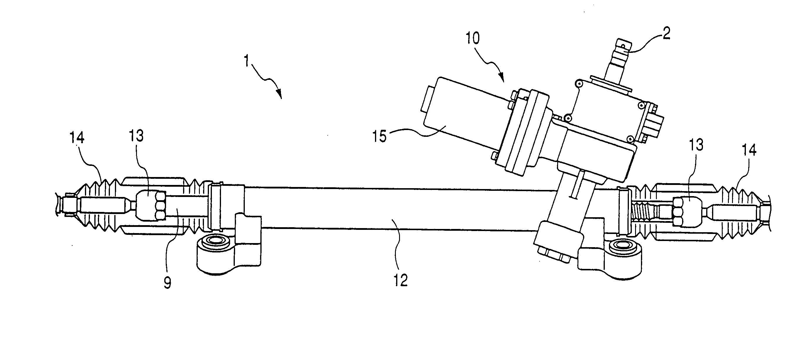
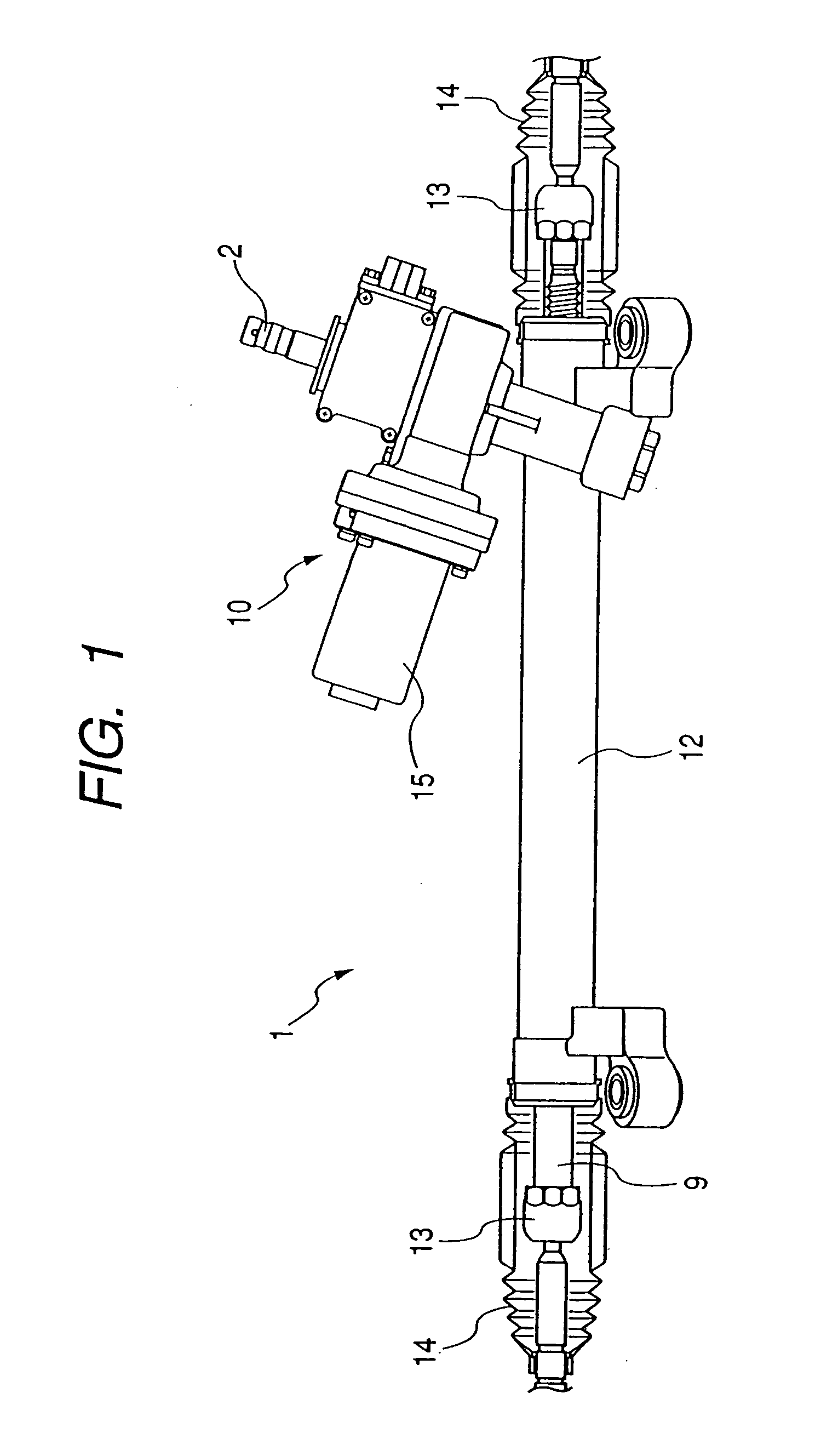
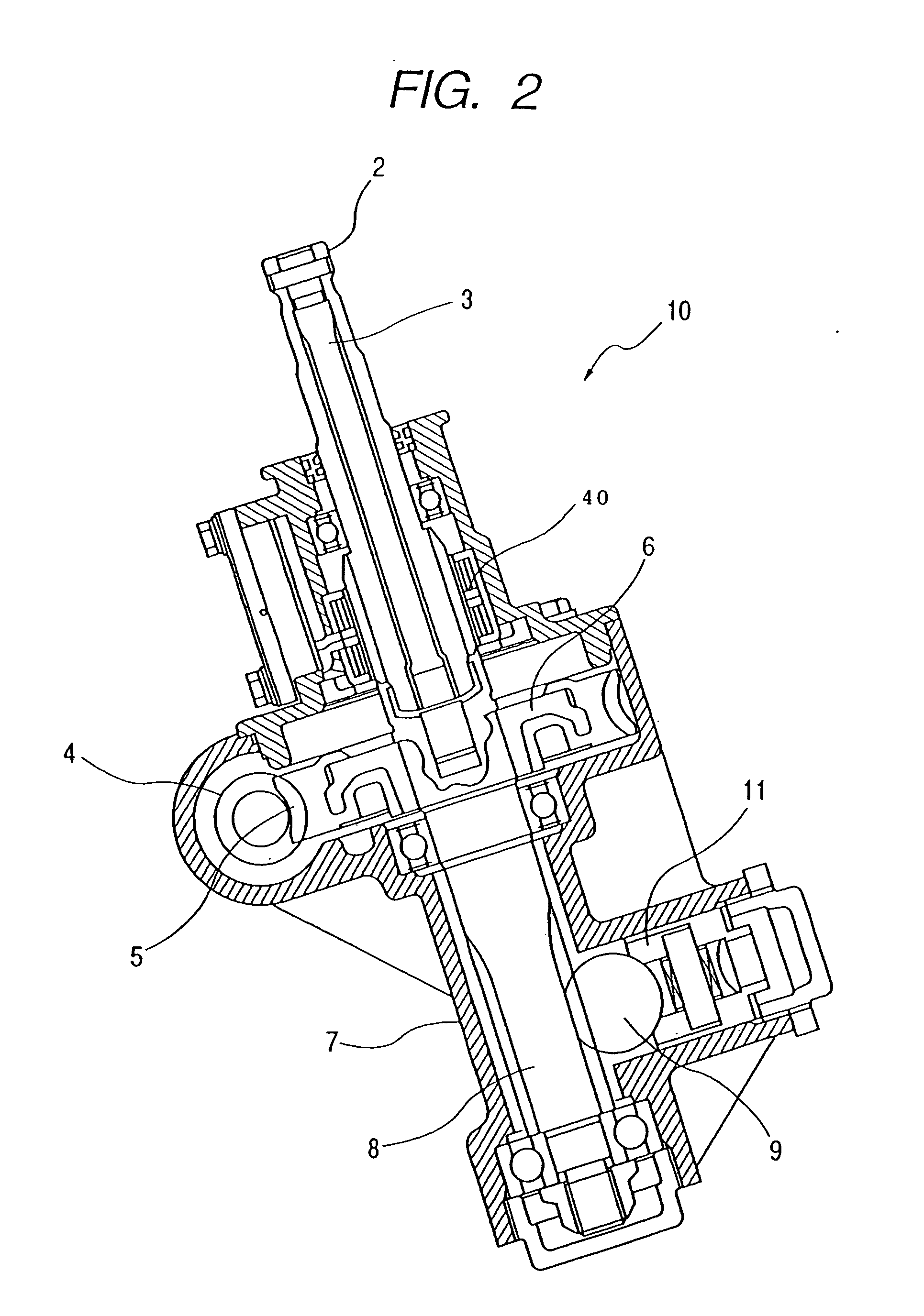
[0033]FIG. 1 is a front view (partially exploded) showing an electric power steering system to which an example of the present invention is applicable, and FIG. 2 is an axial cross-sectional view showing an auxiliary steering input portion. A general pinion assist type electric power steering system 1 comprises an auxiliary steering input portion 10 and a cylindrical sleeve 12 in which a rack shaft 9 coupled to the auxiliary steering input portion 10 has been inserted.

[0034] Referring to FIG. 2, to an input shaft 2 of the auxiliary steering input portion 10, there is coupled a stee...


PUM

PropertyMeasurementUnit
depthaaaaaaaaaa
depthaaaaaaaaaa
depthaaaaaaaaaa

Abstract

A reduction gear including: a worm wheel, the tooth skin portion of which is at least made of macromolecular composite material, and a worm for meshing with the worm wheel concerned, wherein a tooth surface of the worm has been heat-treated by high-frequency induction hardening.

Description

[0001] This application is a continuation-in-part application of International Application No. PCT / JP2004 / 012132, filed on Aug. 18, 2004, which claims the benefit of Japanese Patent Application No. 2003-294438 filed on Aug. 18, 2003.BACKGROUND OF THE INVENTION [0002] 1. Field of the Invention [0003] The present invention relates to an electric power steering system to be used for a vehicle, and more particularly to improvement of a worm to be used for a speed reduction mechanism for transmitting power from a motor. [0004] 2. Related Background Art [0005] In a vehicle such as an automobile, in order to decrease a manual steering force caused by steering a steering wheel, an electric power steering system for electrically applying an auxiliary steering force has been used. In order to apply a motor driven auxiliary steering force to a rack shaft, an electric motor has been used. The steering force from the steering wheel is assisted by an electric motor through a speed reduction mecha...

Claims


Application Information

Patent Timeline
Patent Type & Authority Applications(United States)
IPC IPC(8): B62D5/04C21D1/10C21D9/32F16H55/06F16H55/22
CPCB62D5/0409C21D1/10Y10T74/19828F16H55/06F16H55/22C21D9/32Y02P10/25
Inventor KOYAMA, TAKASHIKAWAMURA, YUJIENDO, TOSHIHITO
Owner NSK LTD
Why Eureka
Try Eureka