
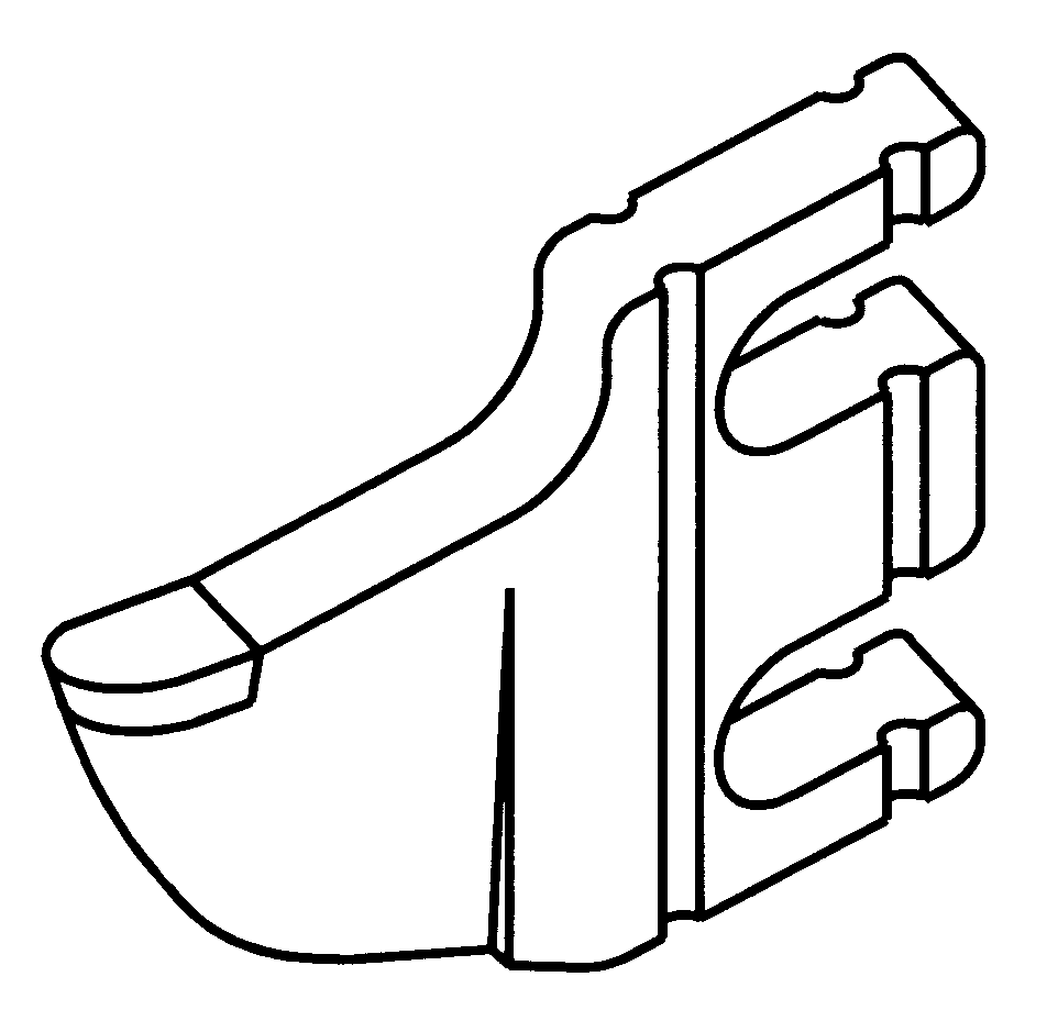
Configurations and designs for stump grinding teeth and corresponding holding

Inactive Publication Date: 2005-08-11
CAO GUOFANG
View PDF5 Cites 5 Cited by
  • Summary
  • Abstract
  • Description
  • Claims
  • Application Information

AI Technical Summary

Benefits of technology

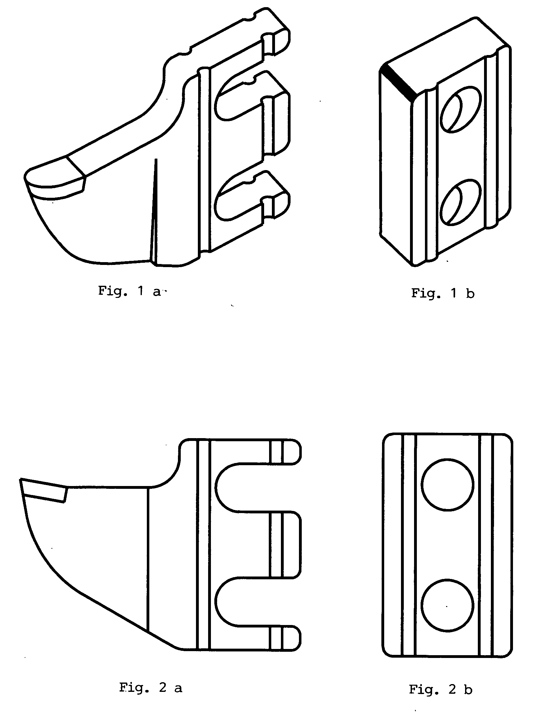
[0005] Present invention provides an improved design and configuration for installing teeth to the rotary disc, by making open slots on the teeth, so that installing teeth will take less time, and consequently, tree stump cutting can be made more efficient.

Problems solved by technology

The disadvantage of the current art is that in order to replace a cutting tooth, the bolts have to be loosened and completed removed.
It's a time-consuming process when damages to cutting tooth or other parts of the cutting machine require replacement of some teeth.

Method used


Image

  • Configurations and designs for stump grinding teeth and corresponding holding
  • Configurations and designs for stump grinding teeth and corresponding holding
  • Configurations and designs for stump grinding teeth and corresponding holding

Examples


Embodiment Construction

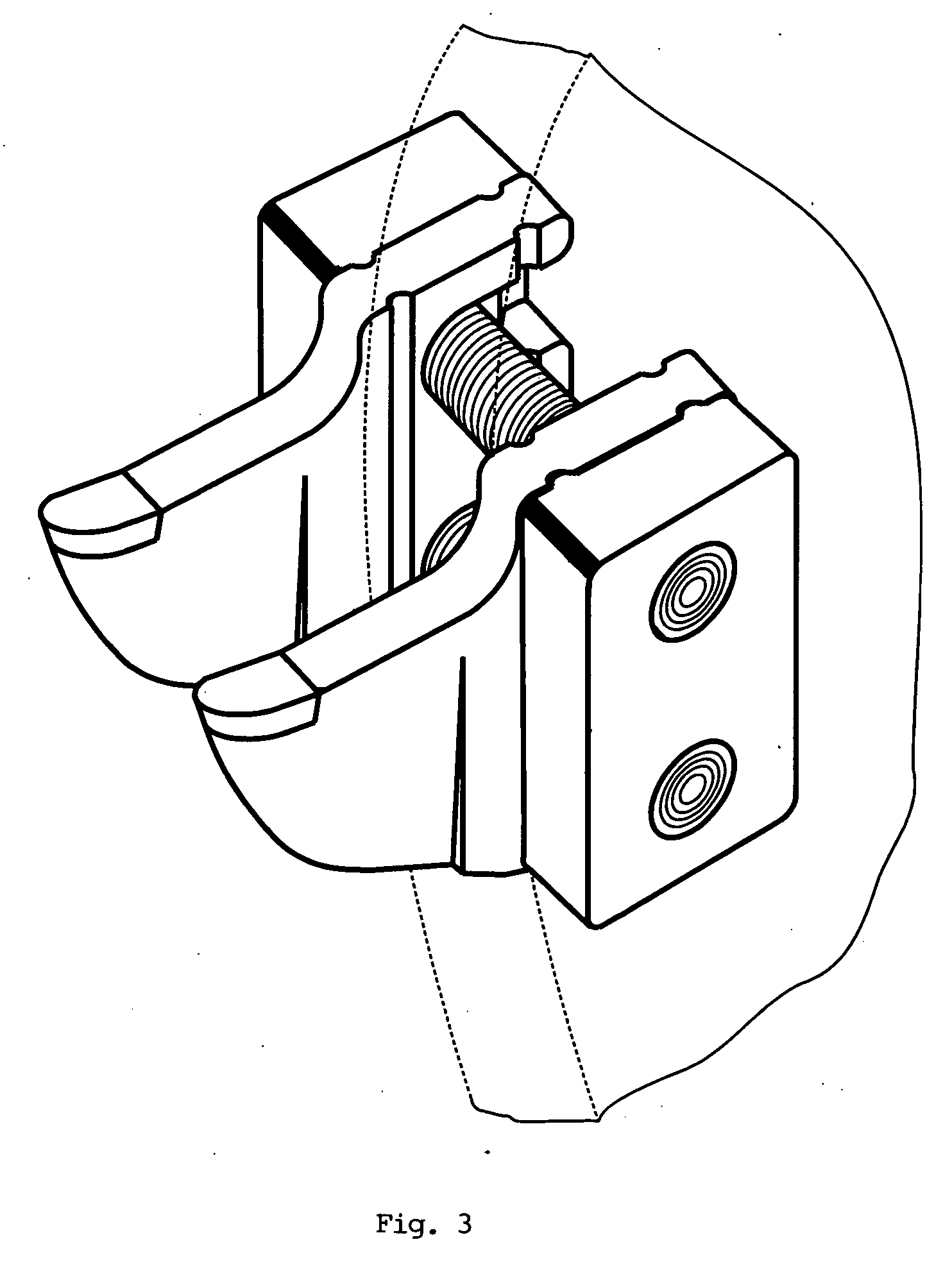
[0020] In FIG. 3, the first preferred configuration of present invention is shown. When a cutting tooth is installed to the rotary disc, two bolts are screwed in so that the holding block presses tightly on one side of the tooth.

[0021] In FIG. 3, and in all other drawings of present invention, ribs and grooves are made on tooth and holding block to provide better alignment at time of installation, and also to provide better clamping effect.

[0022] Two bolts are commonly used for installation of the tooth and holding block to the rotary disc. However, three or more bolts sometimes can be found, depending on the size of the machines and bolts. Because open slots are used on the tooth, replacement of worn tooth is made easier. Instead of removing the bolts completely, a worker needs only loosen the bolts, take out the worn tooth, and put in a new tooth, and quickly tighten the bolts.

[0023] The slot may be opened tangentially as shown in FIGS. 4a and 5a, instead of centripetally, as s...


PUM


Abstract

A new design and configuration for tree stump cutting tooth and its corresponding holding block. Instead of having holes on the tooth, open slots are used, so that replacement of worn-out tooth is easier, because bolts need only be loosened and not completely removed. The use of rib / groove structure eases the task of alignment at time of installing teeth to disc, and increases the clamping power of the holding block to the tooth.

Description

FIELD AND BACKGROUND OF THE INVENTION [0001] The present invention relates generally to design and configuration of teeth and corresponding holding blocks used on machines for tree stump cutting and grinding. [0002] Modern tree stump cutting and grinding machines in general have a rotary disc (or wheel) driven by motor; the disc has multiple teeth attached at the outer edge of the disc so that when the disc is spinning / rotating, the teeth on the edge repeatedly cuts towards the tree stump, or any work piece. [0003] In all the prior art tooth structures, and in use today, each cutting tooth is installed to the rotary disc in one of two ways: the first is by bolting the tooth directly, through two holes at the back portion of the tooth, to the disc; the second is to have a holding block pressing the outside of a tooth, bolting towards the disc. [0004] The disadvantage of the current art is that in order to replace a cutting tooth, the bolts have to be loosened and completed removed. I...

Claims


Application Information

Patent Timeline
IPC IPC(8): A01G23/06
CPCA01G23/067
Inventor CAO, GUOFANG
Owner CAO GUOFANG
Learn More