Heating resistances and heaters

a heat resistance and heater technology, applied in the field of heat resistance and heaters, can solve the problems of hot spots on the heating face, difficult processing, and hard wire made of such high melting point metal, and achieve the effects of easy control of the pitch “ ” of the repetition unit, easy adjustment, and high precision

Active Publication Date: 2005-08-11
NGK INSULATORS LTD
View PDF12 Cites 14 Cited by
  • Summary
  • Abstract
  • Description
  • Claims
  • Application Information

AI Technical Summary

Benefits of technology

[0033] The advantageous effects of the present invention will be described below referring to FIGS. 1 and 2. FIG. 1(a) is a front view showing a heating resistance 1 according to an embodiment of the present invention, and FIG. 1(b) is a plan view showing a heating resistance 1. Further, FIG. 2(a) is a front view showing a heating resistance 1A according to another embodiment, andFIG. 2(b) is a plan view showing a heating resistance 1A.
[0034]FIG. 1 shows a heating resistance 1 composed of a band 5 made of a conductive material. The band 5 is elongated horizontally in FIG. 1 to form a band- or tape- or cord-shaped body. Many folds 2 extending in a direction perpendicular to the longitudinal direction of the heating resistance 1 are formed in the resistance 1 at a predetermined interval. A pair of wall parts 3a and 3b are formed on the both sides of the fold 2. A pair of wall parts 3a and 3b constitute one repetition unit 3. Further, “λ” represents a length (pitch) of one repetition unit 3, “B” represents an amplitude of the repetition unit 3, and “W” represents a width of the band 5.
[0035]FIG. 2 shows a heating resistance 1A composed of a band 5A made of a conductive material. The band 5A is elongated horizontally in FIG. 2 to form a band- or tape- or cord-shaped body. Many folds 2 extending in a direction perpendicular to the longitudinal direction of the heating resistance 1A are formed in the resistance 1A at a predetermined interval. A pair of wall parts 3a and 3b, or 4a and 4b, are formed on the both sides of the fold 2. A pair of wall parts 3a and 3b constitute one repetition unit 3, and a pair of wall parts 4a and 4b constitute one repetition unit. The repetition units 3 and 4 are continuously formed in one integrated band 5A.
[0036]“λ1” represents a length (pitch) of the repetition unit 3, “B1” represents an amplitude of the repetition unit 3, and “W1” represent a width of the band in the repetition unit 3. Further, “λ2” represents a length (pitch) of the repetition unit 4, “B2” represents an amplitude of the repetition unit 4, and “W2” represents a width of the band in the repetition unit 4. According to the present example, the amplitudes “B1” and “B2” are the same and the pitches “λ1” and “λ2” are the same in the repetition units 3 and 4. The width “W2” is, however, made larger than “W1”. The heating value per a unit length in the repetition unit 4 is made smaller than that in the repetition unit 3 when power is supplied to the heating resistance 1A in the longitudinal direction.
[0037] As can be seen from the examples of FIGS. 1 and 2, according to the heating resistance of the present invention, the pitches “λ”, “λ1”, “λ2”, amplitudes “B”, “B1”, “B2”, and widths “W”, “W1”“W2” in the repetition units 3 and 4 can be changed relatively easily and can be designed and manufactured at a high precision. It is thus possible to appropriately adjust the heating value per a unit length in any part of the heating resistance. For example, in every parts of the heating resistance, the pitch “λ” of the repetition unit can be easily controlled, by changing the position of the fold 2 and the angles of inclination of the wall parts 3a, 3b, 4a and 4b. Further, the amplitude “B” in the repetition unit can be easily controlled by changing the position of the fold 2 and the angles of inclination of the wall parts 3a, 3b, 4a and 4b. Further, the width “W” of the band can be easily adjusted by adjusting the width of the band when the band is produced. When the pitch, amplitude and width of the heating resistance is changed in the band, the band is continuous at interface where the pitch, amplitude or width is changed to prevent the risk of abnormal heat generation and disconnection. Further, the troublesome connecting process described earlier is not necessary for the production.
[0038]FIG. 3 is a plan view showing an example of planar pattern of the heating resistance 1 (or 1A) in a substrate 9 of a heater 8 (or 8A) according to one embodiment of the first aspect of the present invention. Although the substrate 9 substantially has a shape of a disk according to the present example, the shape of the substrate 9 is not particularly limited. Further, although the heating resistance 1 (1A) can be provided on the upper and lower surface of the substrate 9, the heating resistance 1 (1A) may preferably be embedded in the substrate 9. When the heating resistance 1 (1A) is embedded in the substrate 9, FIG. 3 schematically shows the planar pattern of the embedded heating resistance as a perspective projection.

Problems solved by technology

A wire made of such high melting point metal is hard, brittle, hard to deform and thus difficult to process.
However, if the resistance at the connecting part of the heating resistance and the terminal in use is raised, hot spots may be observed on the heating face.
The manufacturing process required for producing the connecting part may become troublesome.

Method used


Image

  • Heating resistances and heaters
  • Heating resistances and heaters
  • Heating resistances and heaters

Examples


example 1

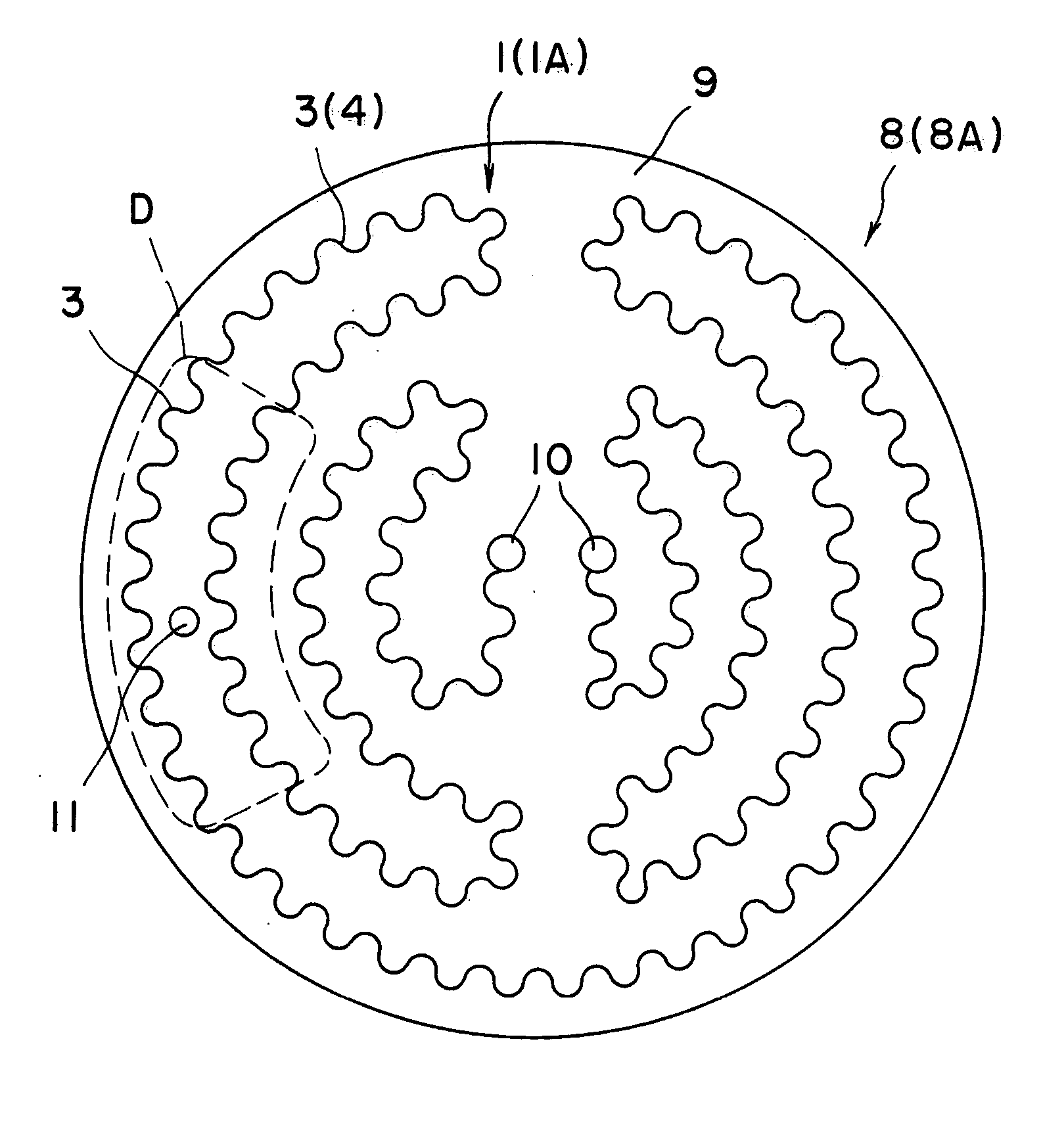
[0060] The heater 8 described referring to FIGS. 3 and 4(a) was produced and the temperature distribution on the surface 9a was measured.

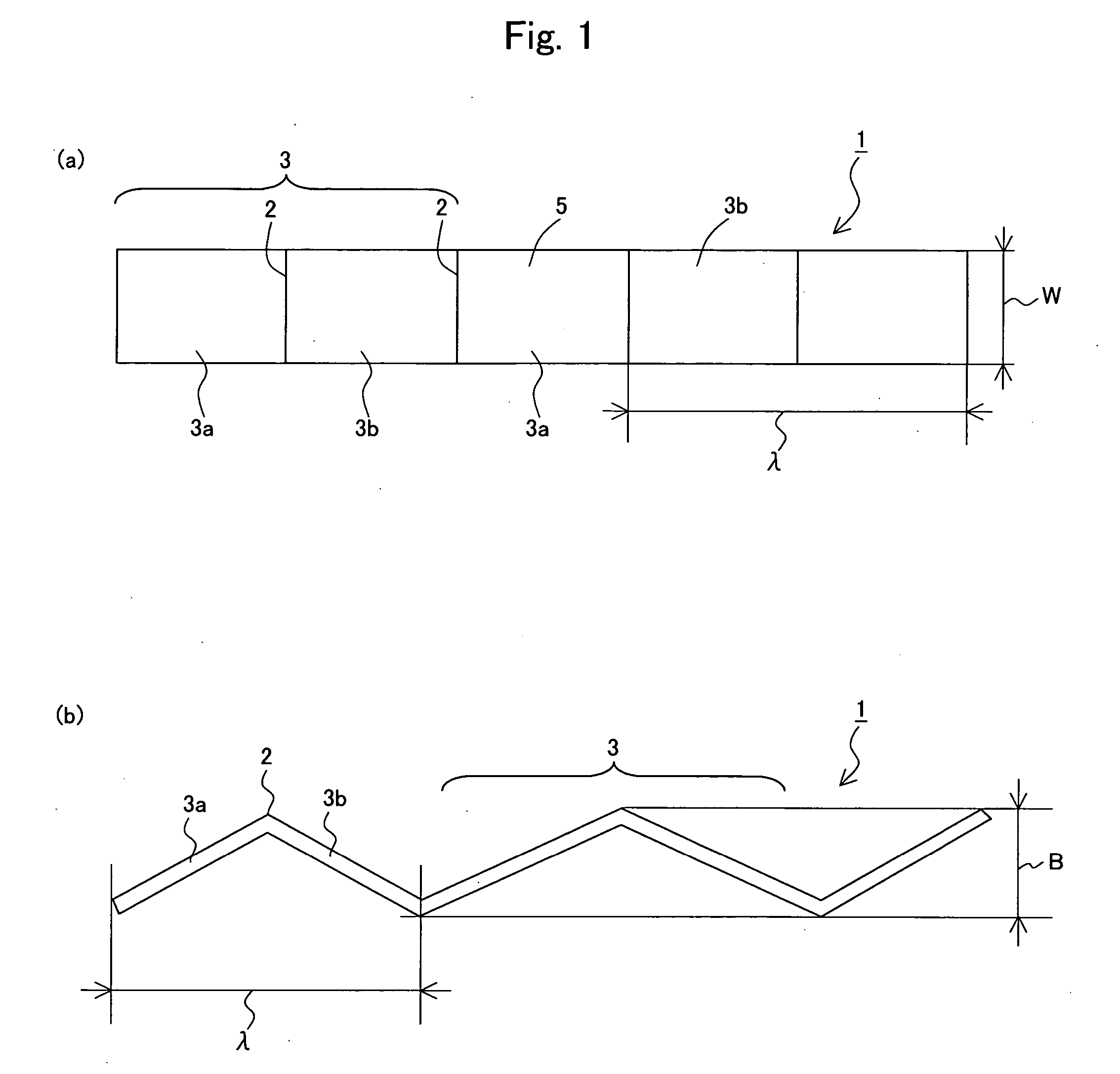
[0061] Specifically, the substrate 9 was made of aluminum nitride sintered body having a diameter Ø of 350 mm and a thickness of 20 mm. The heating resistance 1 shown in FIGS. 1(a) and 1(b) was embedded in the substrate 9. The band 1 was formed of molybdenum and had a thickness of 0.2 mm and width “W” of 10 mm. The pitch “λ” of the repetition unit 3 was 1 to 7 mm and the amplitude “B” of the repetition unit 3 was 3 mm.

[0062] The temperature of the ceramic heater was raised so that the average temperature on the surface 9a reached about 500° C. The temperature distribution on the surface 9a was observed with a thermoviewer. FIG. 11(a) shows the thus obtained contour lines of temperature. The minimum temperature point of 493° C. was near the through holes 11. The maximum temperature point of 503° C. was on the outer periphery on the opposite side t...

example 2

[0063] The heater 8A described referring to FIGS. 3 and 4(b) was produced and the temperature distribution on the surface 9a was measured.

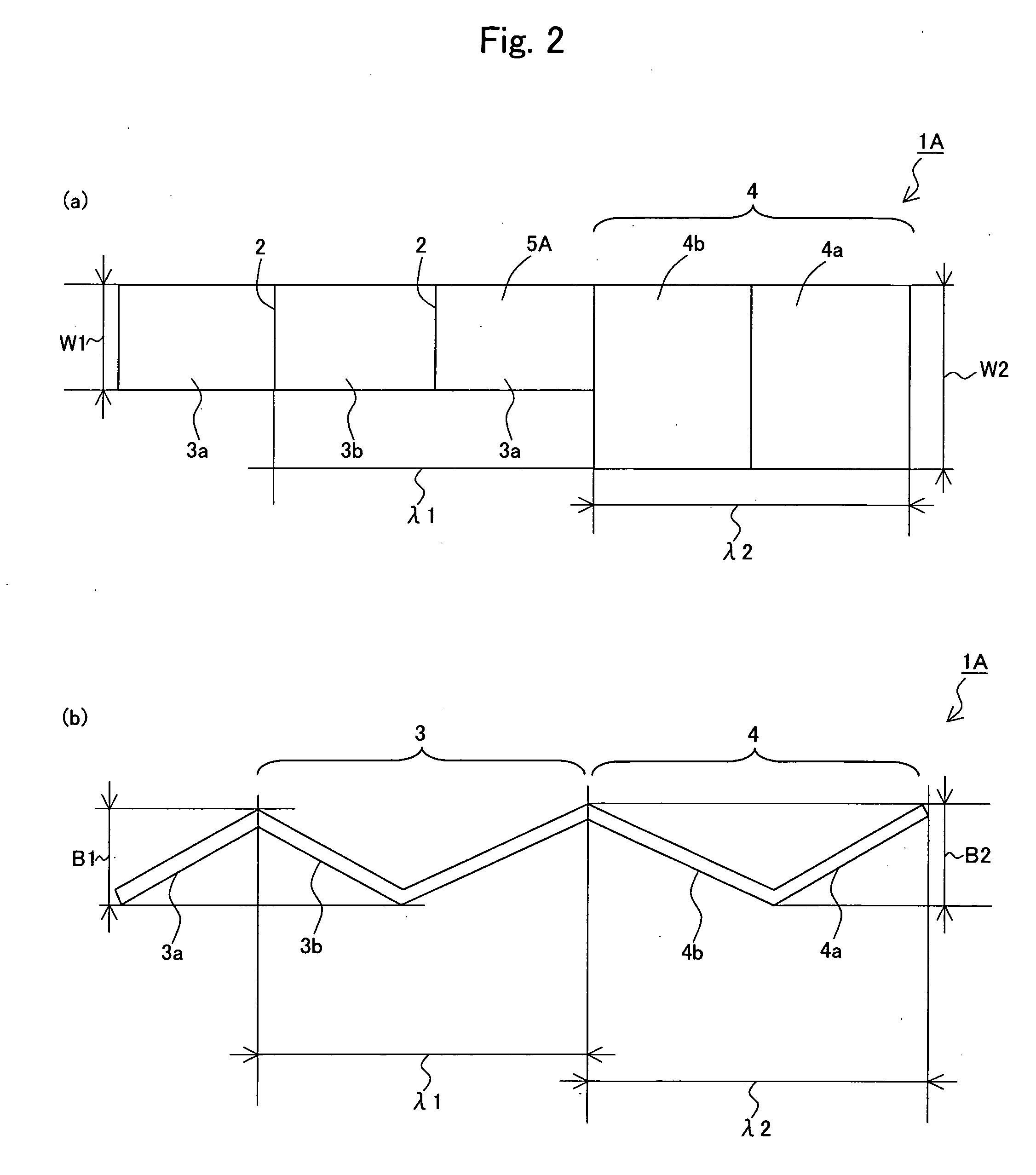
[0064] The heating resistance 1A shown in FIGS. 2(a) and 2(b) was embedded in the substrate 9. The band 5A was formed of molybdenum and had a thickness of 0.2 mm. The width “W1” was 7 mm, pitch “λ1” was 1 to 7 mm and amplitude “B1” was 3 mm in the repetition unit 3. The width “W2” was 10 mm which was larger than W1, pitch “λ2” was 1 to 7 mm and amplitude “B2” was 3 mm in the repetition unit 4.

[0065] The temperature of the ceramic heater was raised so that the average temperature on the surface 9a reached about 500° C. The temperature distribution on the surface 9a was observed with a thermoviewer. FIG. 11(b) shows the thus obtained contour lines of temperature. The minimum temperature point of 494° C. was observed at the outer periphery. The maximum temperature point of 501° C. was near the center of the surface 9a. The difference of the maximum...

example 3

[0066] The heater 18 described referring to FIGS. 6 and 8 was produced and the temperature distribution on the surface 9a was measured.

[0067] Specifically, the substrate 9 was made of aluminum nitride sintered body had a diameter Ø of 350 mm and a thickness of 20 mm. The heating resistance 12 shown in FIG. 6 was embedded in the substrate 9. The band 20 was formed of molybdenum and had a thickness of 0.2 mm and a width “W” of 10 mm. The pitch “λ” was 1 to 7 mm the winding diameter “E” was 4 mm in the repetition unit 13.

[0068] The temperature of the ceramic heater was raised so that the average temperature on the surface 9a reached about 500° C. The temperature distribution on the surface 9a was observed with a thermoviewer. The difference of the maximum and minimum temperatures was 8° C. to prove that the temperature uniformity on the surface can be considerably improved.


PUM


Abstract

A heating resistance 1 comprises a shaped body of a band made of a conductive material obtained by bending the band in a shape of a wave. The heating resistance 1 is fixed to a substrate made of an insulating material to obtain a heater. Alternatively, the heating resistance comprises a wound body of a band made of a conductive material. According to the present invention, the heating value per a unit length can be easily designed and changed, and the reliability can be improved and abnormal heat generation can be prevented at the interface where the heating value per a unit length is changed.

Description

[0001] This application claims the benefits of Japanese Patent Application P2004-1725 filed on Jan. 7, 2004, the entirety of which is incorporated by reference. BACKGROUND OF THE INVENTION [0002] 1. Field of the Invention [0003] The invention relates to a heating resistance and heater suitable to, for example, heating semiconductors, whose temperature distribution can be easily controlled. [0004] 2. Related Art Statement [0005] In a system for producing semiconductors, a ceramic heater has been applied for heating a wafer so as to deposit a semiconductor thin film on the wafer from gaseous raw materials such as silane gas by means of thermal CVD or the like. In such ceramic heater, it is required to make the temperature of the heating face and the semiconductor wafer mounted thereon uniform at a high precision. [0006] It has been known several techniques for reducing temperature distribution on the heating (mounting) face of the ceramic heater. For example, so-called two-zone heater...

Claims


Application Information

Patent Timeline
Patent Type & Authority Applications(United States)
IPC IPC(8): H05B3/10H01L21/00H01L21/02H05B3/14H05B3/16H05B3/18H05B3/74
CPCH01L21/67103H05B3/748H05B3/143
Inventor GOTO, YOSHINOBU
Owner NGK INSULATORS LTD
Why Eureka
Try Eureka