Core gluing device for a rewinding machine and related method

a rewinding machine and core gluing technology, which is applied in the direction of fluid heaters, lighting and heating apparatus, heating types, etc., can solve the problems of frequent maintenance, limited production capacity of the rewinding machine, and inability to adjust the amount of glue applied

Inactive Publication Date: 2005-08-11
PAPER CONVERTING MASCH CO INC
View PDF7 Cites 5 Cited by
  • Summary
  • Abstract
  • Description
  • Claims
  • Application Information

AI Technical Summary

Benefits of technology

[0012] An object of the present invention is to eliminate the drawbacks of the prior art by providing a core gluing device that permits the control of t...

Problems solved by technology

It operates irregularly with high density glues, requires frequent maintenance for cleaning, and does not permit adjustment of the amount of glue applied.
Due to the up-down times of the bar and to the time it remains in the tank to pick up the glue, the speed of the glue distribution unit is limited and therefore the production capacity of the rewinding ma...

Method used


Image

  • Core gluing device for a rewinding machine and related method
  • Core gluing device for a rewinding machine and related method

Examples


Embodiment Construction

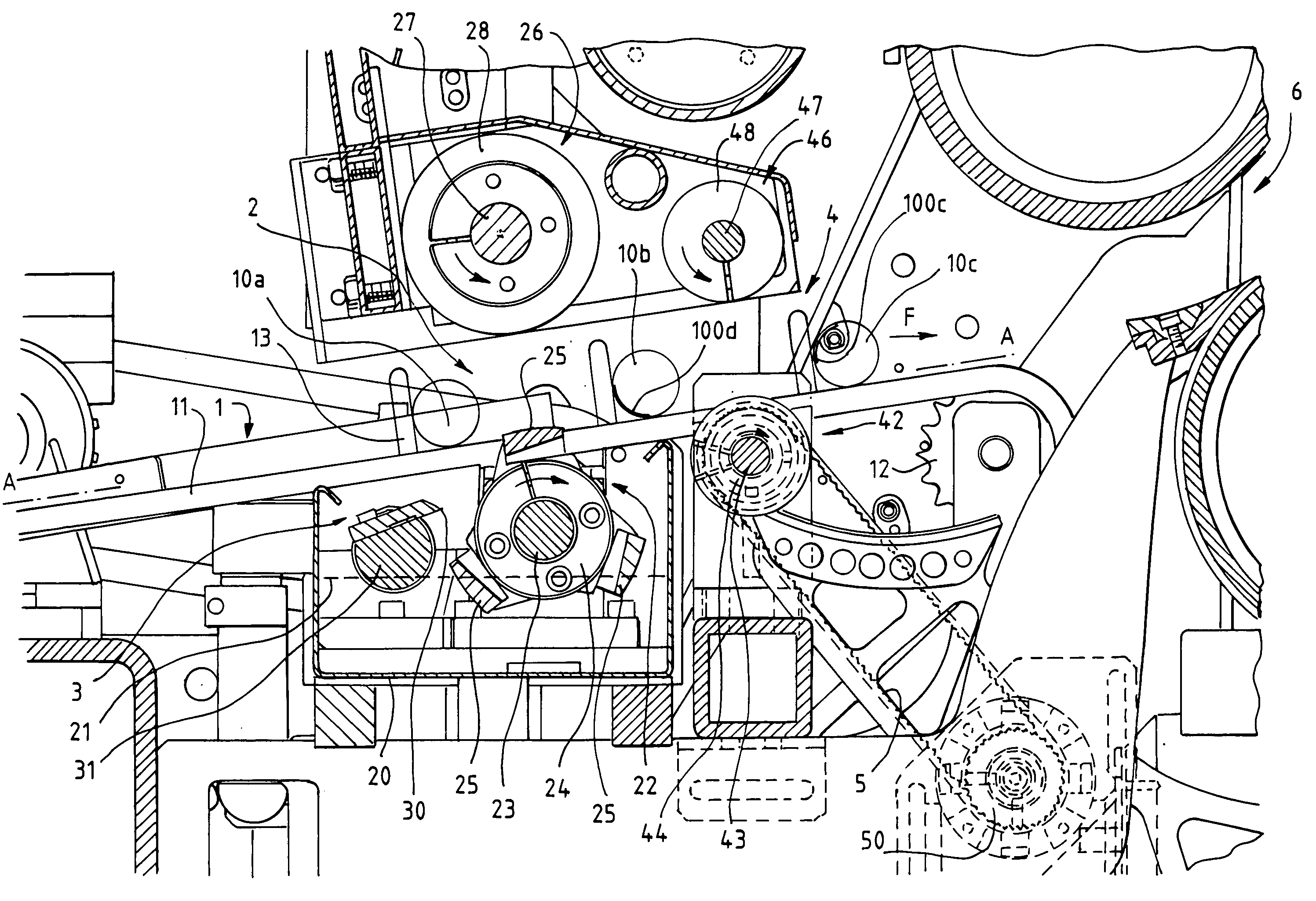
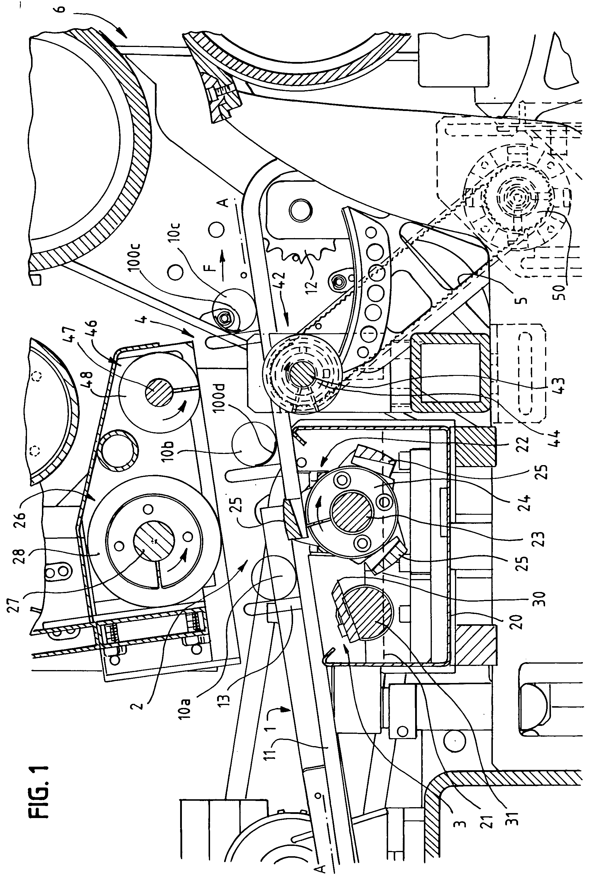
[0027] The gluing device according to the invention comprises a conveyor 1 designed to convey a plurality of tubular cores (10a, 10b, 10c), a glue application unit 2 designed to apply the glue on the outer surface of said cores (10a, 10b, 10c), and positioning devices 4 designed to position the cores (10a, 10b, 10c) in a suitable position for their insertion between the winding rollers of a winding unit 6 (illustrated partially) forming part of the rewinding machine.

[0028] The conveyor 1 comprises a conveying surface A-A defined by the arrangement of conveying chains 11, sloping slightly upwards, on which the cores (10a, 10b, 10c) are conveyed in a feed direction indicated by the arrow F. In the solution shown, the conveyor 1 comprises one or more chains 11 driven by motorized crown gears 12 in order to feed the cores forward.

[0029] The conveyor chains 11 are fitted with a plurality of pusher devices 13 in the form of plates that protrude upwards, substantially square to the conve...


PUM

PropertyMeasurementUnit
Angleaaaaaaaaaa
Diameteraaaaaaaaaa
Speedaaaaaaaaaa

Abstract

A core gluing device for a rewinding machine comprises a conveyor (1) designed to convey cores (10a, 10b, 10c) along a core conveying surface (A-A), a gluing unit (2) comprising a first gluing roller (22) which picks up the glue from a glue container (20) and a second gluing roller (26) opposed to the first gluing roller, so that each core (10a, 10b, 10c) can pass between the two gluing rollers (22, 26) for application of a trace of glue (100b, 100c) on it. The gluing rollers (22, 26) are driven at different speeds to control the width of the trace of glue to be applied to the core, and positioning devices (4) are provided, arranged downstream of the gluing devices (2) and upstream of a log winding unit (6) of the rewinding machine for the correct positioning of the core (10c) with the related trace of glue (100c), before insertion between the winding rollers.

Description

BACKGROUND [0001] The present invention refers to a device and to a method for gluing cores of a rewinding machine. [0002] As is known, a rewinding machine is used for the formation of reels of sheet material originating from large parent reels. [0003] Generally the sheet material is wound on tubular cores, which are appropriately fed towards the winding unit of the rewinding machine. For this purpose, upstream of the winding unit of the rewinder there is a gluing unit which applies a strip of glue on the outer surface of the cores. In this way, when the core comes into contact with the winding rollers, the end edge of the sheet material grips the glue deposited on the core, permitting winding of the sheet material on the core for formation of the reel. [0004] The European patent EP 0.697.988 describes a gluing unit of the overflow type. The glue comes out of a slot positioned according to a directrix of the core by overflowing and is applied on the cores when they pass over the slo...

Claims


Application Information

Patent Timeline
IPC IPC(8): B65H19/28F24D3/08F24F1/02F24F5/00F24H4/02
CPCB65H19/283F25B2339/047B65H2301/41812
Inventor CASELLA, SERGIOBAGIONI, MAURO
Owner PAPER CONVERTING MASCH CO INC
Why Eureka
Try Eureka