Backup power system

Inactive Publication Date: 2005-08-11
FARKAS OTTO
View PDF26 Cites 27 Cited by
  • Summary
  • Abstract
  • Description
  • Claims
  • Application Information

AI Technical Summary

Benefits of technology

[0028] Using the backup power system embodying the present invention will thus accurately and rel

Problems solved by technology

Sensitive loads, such as computers, data processing equipment, communications equipment, and the like, require stable and uninterrupted power.
However, battery power is not sufficient for large power grids, such as might be associated with utility power sources.
Furthermore, battery failures due to constant charging are a common problem in the standby power generation industry and thus battery backup systems may have problems, including reliability problems.
However, during longer interruption of utility power, synchronous condensers may be inadequate.
Once the condenser turns into a generator, the re-connect of the utility out of phase becomes a critical issue.
If a utility breaker is not immediately opened, the generator will back feed the entire grid and may also fail due to overload.
However, once the generator is connected in parallel to the utility, any disturbance on the utility line, such as lightning strikes or the like, may have direct consequences on these very same monitoring and protection devices.
In some cases, these devices may fail to detect a power interruption in time or fail completely due to problems associ

Method used


Image

  • Backup power system
  • Backup power system
  • Backup power system

Examples


Embodiment Construction

[0039] Other objects, features and advantages of the invention will become apparent from a consideration of the following detailed description and the accompanying drawings.

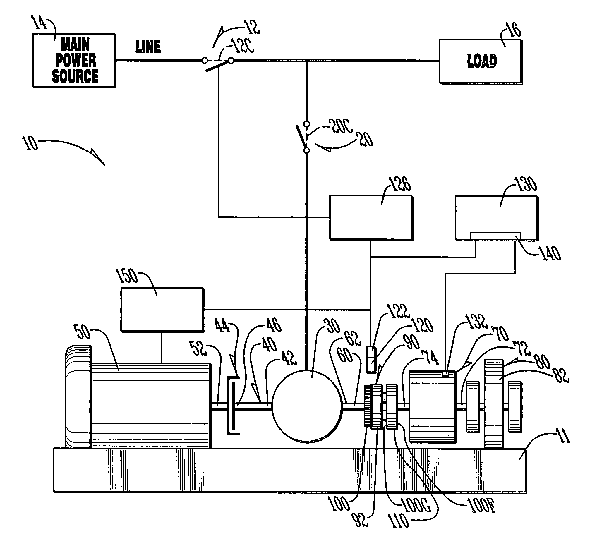
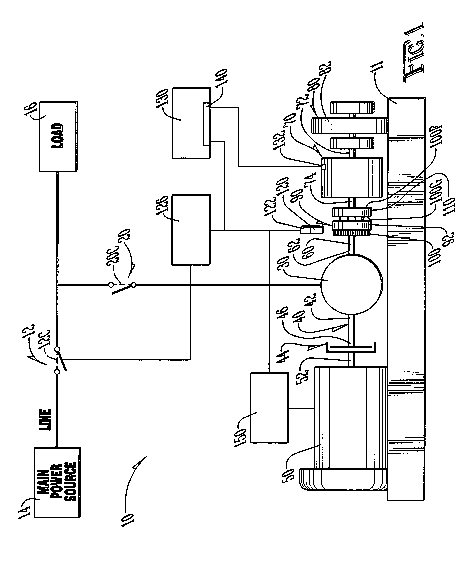
[0040] Referring to FIGS. 1-3, it can be understood that the present invention is embodied in a backup power system 10. System 10 can be mounted on a skid 11.

[0041] System 10 comprises a line breaker switch 12 which is adapted to be electrically interposed between a main power source 14, such as a utility, and a load 16. Line breaker switch 12 has a closed condition which is indicated in FIG. 1 by dotted lines 12C, which electrically connects the main power source to the load and an open condition which is shown in solid lines in FIG. 1 which disconnects the load from the main power source.

[0042] A generator breaker switch 20 is electrically connected to the main power source in parallel with the load. Generator breaker switch 20 has a closed condition shown in FIG. 1 by dotted lines 20C and an open condition ...


PUM


Abstract

A backup power system is connected in parallel to a load which is powered via a power line connecting that load to a main power source, such as a utility. The backup system includes a generator/condenser unit that is coupled to a flywheel unit to maintain the flywheel of that flywheel unit rotating at a preset speed during normal power system operation and is also connected to a thermal engine to supply power to the load via the generator/condenser unit when there is an interruption of power from the main power source. A shaft coupling unit slidably couples the generator/condenser unit to the flywheel unit. The shaft coupling unit includes a slip plate. Part of the shaft coupling unit rotates in accordance with the operation of the generator/condenser unit, while with the slip plate rotates in accordance with the flywheel of the flywheel unit. Rotation of the generator/condenser unit is monitored by a sensor and rotation of the flywheel is also monitored. A circuit generates a signal which activates the thermal engine when rotational speed of the generator/condenser unit differs from rotational speed of the flywheel by a preset margin.

Description

TECHNICAL FIELD OF THE INVENTION [0001] The present invention relates to the general art of electrical transmission, and to the particular field of emergency and standby electrical power. BACKGROUND OF THE INVENTION [0002] Sensitive loads, such as computers, data processing equipment, communications equipment, and the like, require stable and uninterrupted power. Accordingly, many such items include battery backup power supplies. However, battery power is not sufficient for large power grids, such as might be associated with utility power sources. Furthermore, battery failures due to constant charging are a common problem in the standby power generation industry and thus battery backup systems may have problems, including reliability problems. [0003] Therefore, there is a need for a standby and backup power system that does not require batteries. [0004] Synchronous condensers and synchronous motors are used on power systems where large amounts of reactive KVA are needed for power fa...

Claims


Application Information

Patent Timeline
IPC IPC(8): F01K13/00
CPCF01K13/00
Inventor FARKAS, OTTO
Owner FARKAS OTTO
Why Eureka
Try Eureka