Differential preamplifier having balanced resistor network

a resistor network and preamplifier technology, applied in the field of preamplifier circuits, can solve the problems of large input offset, poor switching recovery time, and rarely perfectly matching of transistors, and achieve the effects of reducing input stage offset, improving input dynamic range, and fast switching times

Active Publication Date: 2005-08-11
TEXAS INSTR INC
View PDF5 Cites 1 Cited by
  • Summary
  • Abstract
  • Description
  • Claims
  • Application Information

AI Technical Summary

Benefits of technology

[0003] The present invention is designed for AC signal pre-amplifiers, for use in among other things, the first stage of a MR sensor coupled preamplifier. The present invention reduces the current mismatch at the base of the first stage transistors, resulting in faster switching times by reducing input stage offset and, hence improving input dynamic range.

Problems solved by technology

Disadvantageously, transistors are rarely perfectly matched, which gives rise to various offsets due to feedback current mismatches.
A current mismatch results in a large input offset and bad switching recovery time due to the offset.
But feedback loops give rise to other problems such as increased recovery time and increased control circuit complexity.

Method used


Image

  • Differential preamplifier having balanced resistor network
  • Differential preamplifier having balanced resistor network
  • Differential preamplifier having balanced resistor network

Examples


Embodiment Construction

[0006] When used with ac signal amplifiers, the present invention reduces current mismatch and results in faster switching times by reducing input stage offset. The present invention also improves input dynamic range. In order to optimize the performance of the present invention, no trim or tuning is required.

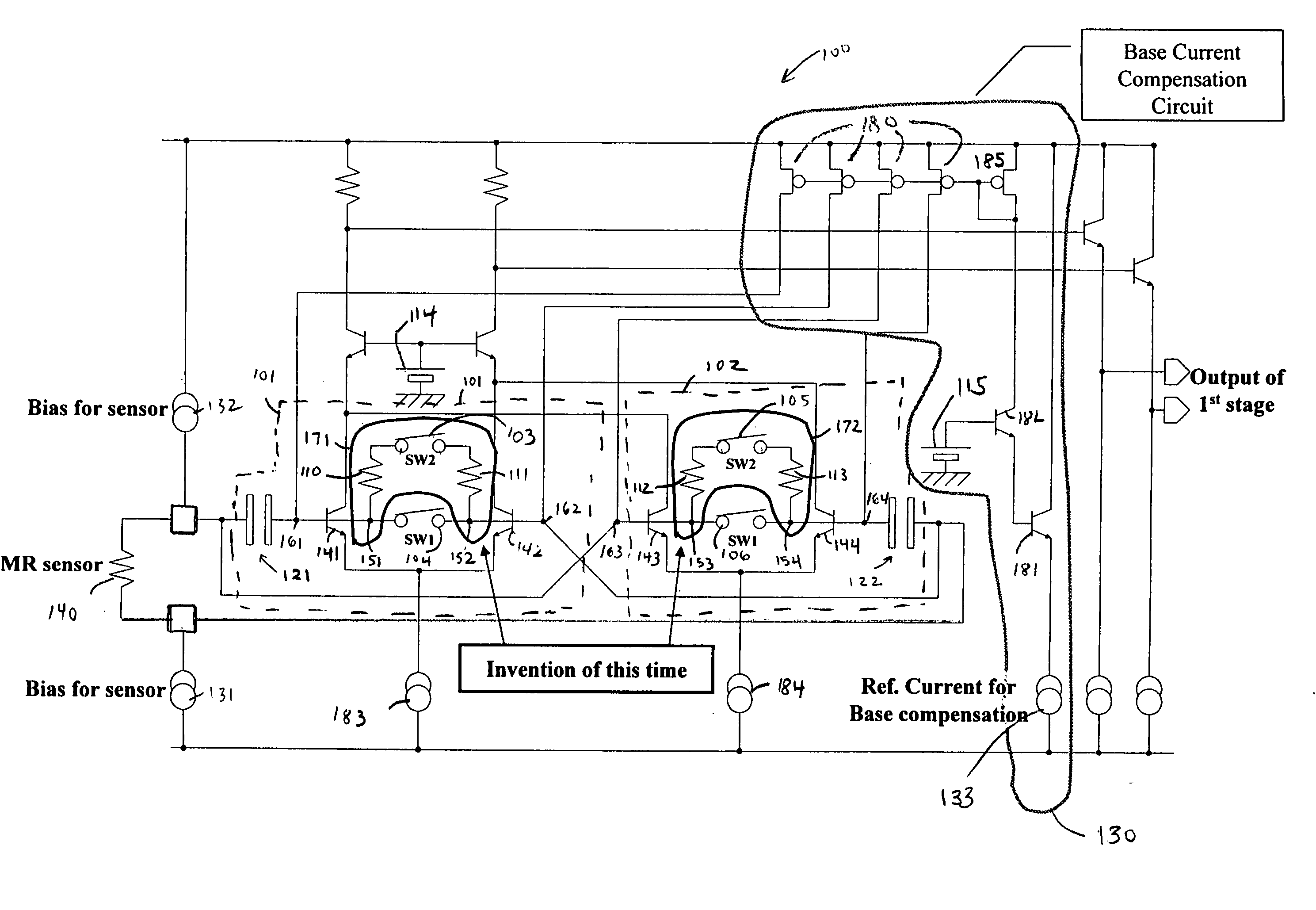
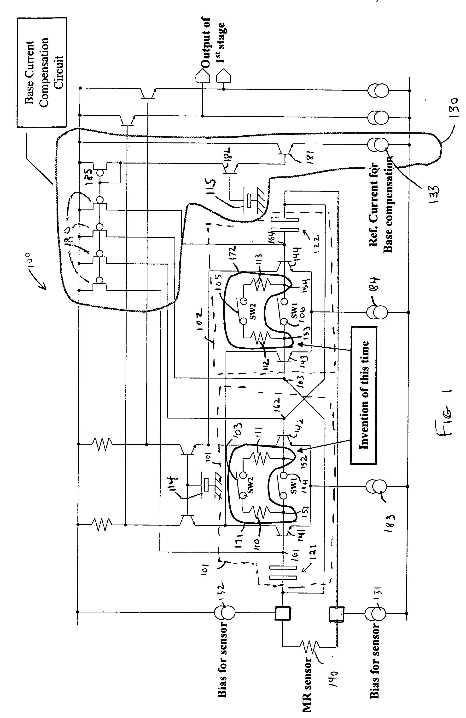
[0007] Referring to FIG. 1, MR sensor 140 is biased by a first current source 131 and a second current source 132 and is capacitively coupled to the preamplifier through first capacitor 121 and second capacitor 122. First capacitor 121 has a first terminal and second terminal, the second terminal being coupled at node 161 to the first circuit 101 of the preamplifier circuit. Second capacitor 122 has a first terminal and a second terminal, the second terminal being coupled at node 164 to the second circuit 102 of the preamplifier. The first terminal of the first capacitor 121 is cross-coupled to the second circuit 102 of the preamplifier circuit at node 163 and the first termin...


PUM


Abstract

The present invention comprises a pair of circuits (171, 172) within the first stage (100) of an AC signal pre-amplifier. The present invention reduces the current mismatch at the base of the first stage transistors (141, 142, 143, 144) resulting in faster switching times by reducing input stage offset and, hence improving input dynamic range.

Description

FIELD OF THE INVENTION [0001] The present invention relates to pre-amplifier circuits which are coupled to magneto-resistive (“MR”) read / write heads utilized in hard disk drives (“HDDs”). BACKGROUND OF THE INVENTION [0002] The typical MR read / write head comprises a sensor or element that senses ambient magnetic fields at the head, causing a relative change in MR resistance. The change or variation produces a current variation that is received in the preamplifier. AC coupling, typically using capacitors, between the MR sensor and the amplifier stages prevents the amplifier input stages from being overloaded by DC voltages across the MR elements. A number of techniques have been developed to shorten DC settling transients and hence increase recovery times of the MR element. These techniques have been developed to increase the speed of the preamplifier. Conventional ac signal amplifiers use a transistor circuit coupled to the bases of the pre-amplifier transistor differential pairs to ...

Claims


Application Information

Patent Timeline
Patent Type & Authority Applications(United States)
IPC IPC(8): G06G7/12H03F3/45
CPCH03F3/45089H03F3/45627H03F2203/45616H03F2203/45604H03F2203/45564
Inventor HIROTSUGU, YUKIHISAHANAJIMA, NAOYUKIOGIWARA, HISAO
Owner TEXAS INSTR INC
Why Eureka
Try Eureka