Micromechanical resonator device having a desired mode shape

a micromechanical and resonator technology, applied in the direction of impedence networks, electrical devices, etc., can solve the problems of high ghz range mechanical resonators demonstrated so far that they cannot be directly coupled to antennas in rf systems, and achieve the effect of reducing mechanical losses on the substra

Active Publication Date: 2005-08-11
RGT UNIV OF MICHIGAN
View PDF1 Cites 21 Cited by
  • Summary
  • Abstract
  • Description
  • Claims
  • Application Information

AI Technical Summary

Benefits of technology

[0016] In carrying out the above object and other objects of the present invention, a micromechanical resonator device having a desired mode shape is provided. The device includes a substrate and a resonator having inner and outer peripheries. The desired mode shape is characterized by a plurality of quasi-nodal points located about the peripheries. Portions of the resonator exhibit extensional characteristics. The peripheries exhibit both radial and tangential displacements at resonance. The device also includes a non-intrusive support structure anchored to the substrate to support the resonator above the substrate and attached to the resonator at at least one of the quasi-nodal points to reduce mechanical losses to the substrate.

Problems solved by technology

Unfortunately, however, although their Q's and frequencies are now sufficient, the impedances of the GHz range μmechanical resonators demonstrated so far are still too high to allow direct coupling to antennas in RF systems, where matching to impedances in the range of 50 Ω and 330 Ω is often required.

Method used


Image

  • Micromechanical resonator device having a desired mode shape
  • Micromechanical resonator device having a desired mode shape
  • Micromechanical resonator device having a desired mode shape

Examples


Embodiment Construction

)

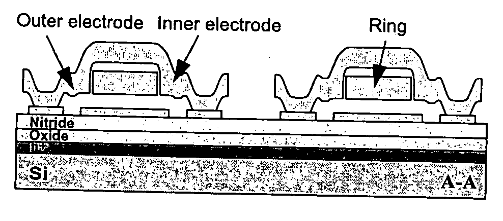
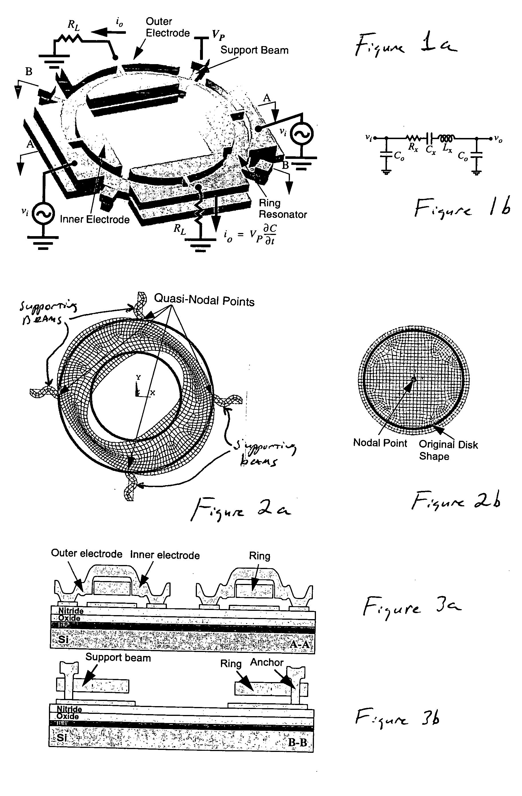
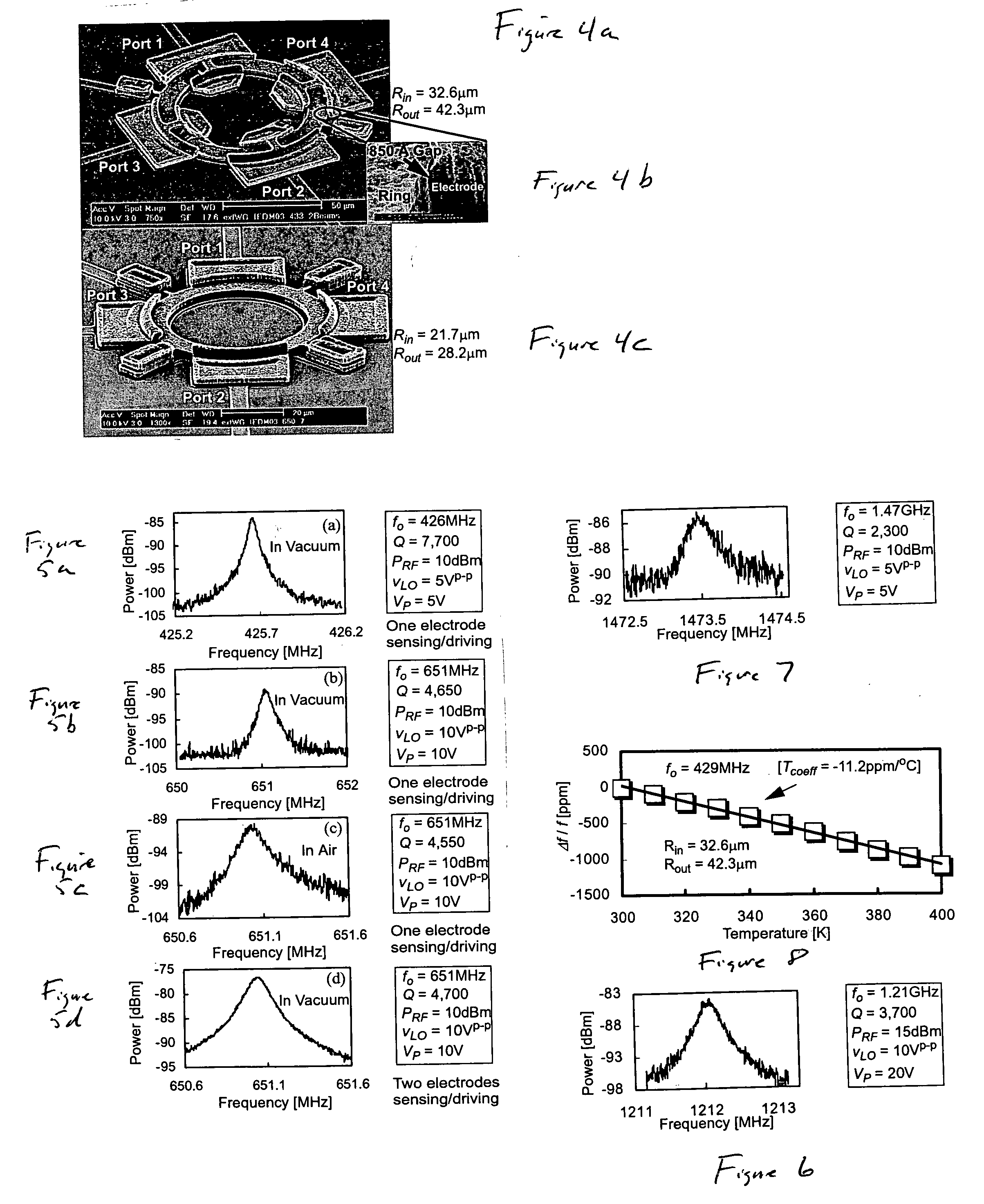
[0032] One embodiment of the present invention provides a micromechanical resonator device having an extensional wine-glass mode shape. This resonator operates in a special resonant mode, with a shape shown in FIG. 2a, that combines aspects of two previously demonstrated modes, namely, the extensional radial contour vibration mode [1] [2] and the wine-glass disk vibration mode [3], together with the geometric advantages of a ring structure [4], to achieve the best of each design. In particular, this extensional wine-glass resonator design allows: (1) a high resonance frequency, owing to its use of an extensional mode; (2) a low motional impedance, due to its ring-geometry, which offers a larger capacitive transducer overlap area than provided by the perimeter of a filled disk; and (3) higher Q, since its mode shape resembles a wine-glass-like mode [3], which allows its support structure to avoid a centrally located stem and thereby reduce anchor losses. With this design, frequencie...


PUM


Abstract

A micromechanical resonate device having an extensional wine-glass mode shape is described herein. Different embodiments of the device may employ vibrating polysilicon micromechanical ring resonators, utilizing a unique extensional wine-glass mode shape to achieve lower impedance than previous UHF resonators at frequencies as high as 1.2-GHz with a Q of 3,700, and 1.47-GHz (highest to date for polysilicon micromechanical resonators) with a Q of 2,300. The 1.2-GHz resonator exhibits a measured motional resistance of 560 kΩ with a dc-bias voltage of 20V, which is 6× lower than measured on radial contour mode disk counterparts at the same frequency, and which can be driven down as low as 2 kΩ when a dc-bias voltage of 100V and electrode-to-resonator gap spacing of 460 Å are used. The above high Q and low impedance advantages, together with the multiple frequency, on-chip integration advantages afforded by electrostatically-transduced μmechanical resonators, may be utilized in the front-end RF filtering and oscillator functions needed by wireless communication devices.

Description

CROSS-REFERENCE TO RELATED APPLICATIONS [0001] This application claims the benefit of U.S. provisional application Ser. No. 60 / 520,954, filed Nov. 18, 2003 and entitled “Extensional Wine Glass Resonator.” This application is a continuation-in-part of U.S. application Ser. No. 10 / 737,363, filed Dec. 16, 2003 and entitled “Micromechanical Resonator Device and Method of Making a Micromechanical Device.STATEMENT REGARDING FEDERALLY SPONSORED RESEARCH OR DEVELOPMENT [0002] The invention was made with Government support under DARPA Grant No. F30602-01-1-0573. The Government has certain rights to the invention.BACKGROUND OF THE INVENTION [0003] 1. Field of the Invention [0004] This invention relates to micromechanical resonator devices having desired mode shapes. [0005] 2. Background Art [0006] The following references are referenced herein: [0007] 1. J. Wang, Z. Ren, and C. T.-C. Nguyen, “Self-Aligned 1.14 GHz vibrating radial-mode disk resonators,” TRANSDUCERS '03, pp. 947-950. [0008] 2....

Claims


Application Information

Patent Timeline
Patent Type & Authority Applications(United States)
IPC IPC(8): H03H3/007H03H9/24
CPCH03H3/0072H03H9/2431H03H2009/02503H03H2009/02354H03H9/2436
Inventor NGUYEN, CLARK T.-C.XIE, YUAN
Owner RGT UNIV OF MICHIGAN
Why Eureka
Try Eureka