
Liquid crystal display device, liquid crystal cell, transparent substrate, and method of manufacturing liquid crystal cell

Inactive Publication Date: 2005-08-11
LINKEDIN
View PDF4 Cites 52 Cited by
  • Summary
  • Abstract
  • Description
  • Claims
  • Application Information

AI Technical Summary

Benefits of technology

[0011] It is another object of the present invention to maintain the strength of a glass substrate in the liquid crystal cell capable of outputting a sound.
[0012] It is another object of the present invention to suppress occurrence of an image defect in the liquid crystal display device capable of outputting a sound of a large volume.

Problems solved by technology

Accordingly, there is a disadvantage in that harmful effects such as a decrease in the light quantity of the image and a difficulty in seeing the image due to reflection.
Although it is desirable to form the glass substrates constituting the liquid crystal cell as thin as possible in order to achieve the downsizing / thinning and weight reduction of the liquid crystal display device, defective regions of glass of the glass substrates are decorated and substrate surfaces are prone to be uneven when the glass substrates are thinly formed.
The unevenness of the surfaces of the glass substrates brings an image display failure in the liquid crystal display device, and accordingly, a thickness of each of the glass substrates sandwiching the liquid crystal layer therebetween, which is obtained by processing the glass substrates to be thin, has had a lower limit of approximately 0.6 to 0.7 mm.
Therefore, weights of the glass substrates themselves cannot be reduced sufficiently, and it is difficult to vibrate the entire glass substrate sufficiently, and thus there is a problem that a sufficient volume cannot be ensured.

Method used


Image

  • Liquid crystal display device, liquid crystal cell, transparent substrate, and method of manufacturing liquid crystal cell
  • Liquid crystal display device, liquid crystal cell, transparent substrate, and method of manufacturing liquid crystal cell
  • Liquid crystal display device, liquid crystal cell, transparent substrate, and method of manufacturing liquid crystal cell

Examples


Embodiment Construction

[0036] An embodiment of the present invention is described below in detail with reference to the accompanying drawings.

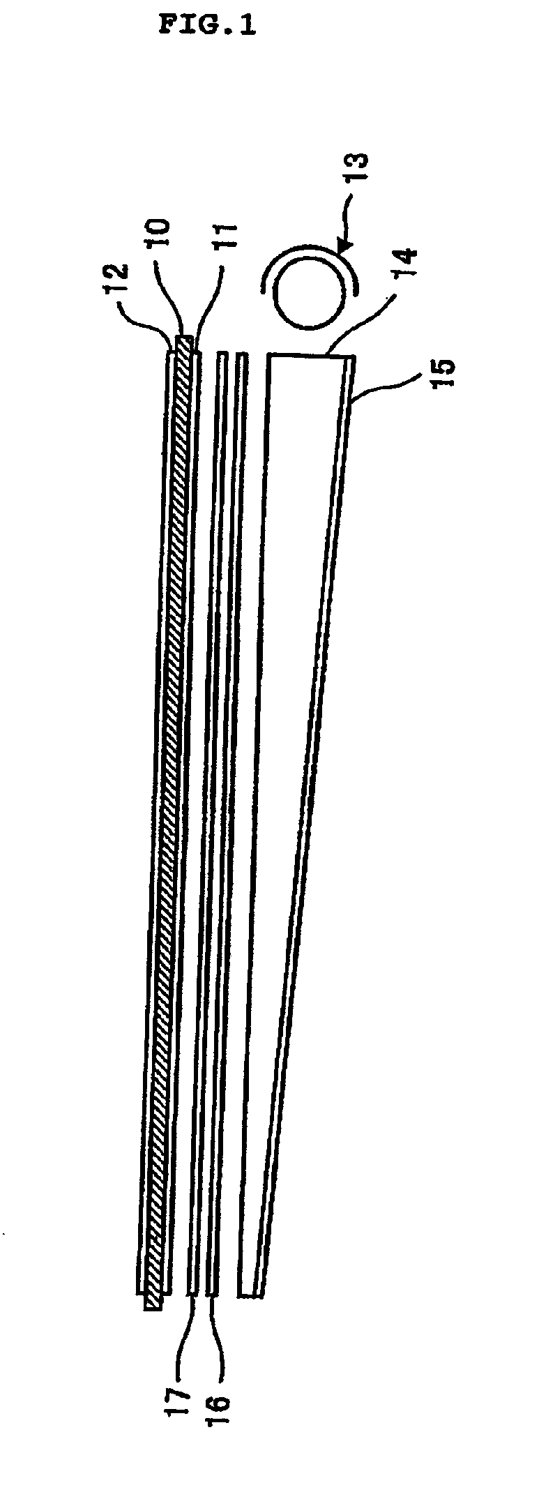
[0037]FIG. 1 is a cross-sectional view showing a liquid crystal display device to which this embodiment is applied. Principal portions of the liquid crystal display device shown in FIG. 1 are composed of a liquid crystal cell 10 which modulates a polarization state of a linear polarization incident thereonto; a polarizing plate 11 provided on a light incident side of the liquid crystal cell 10; a polarizing plate 12 provided on a light emitting side of the liquid crystal cell 10; a backlight 13 which is disposed on a side portion on a backside of the liquid crystal cell 10 and irradiates light onto the liquid crystal cell 10; a light guide member 14 which guides the light from the backlight 13 to an entire surface of the liquid crystal cell 10; a prism sheet 16 which enhances brightness of the light reflected off the light guide member 14 in a front direction; and ...


PUM


Abstract

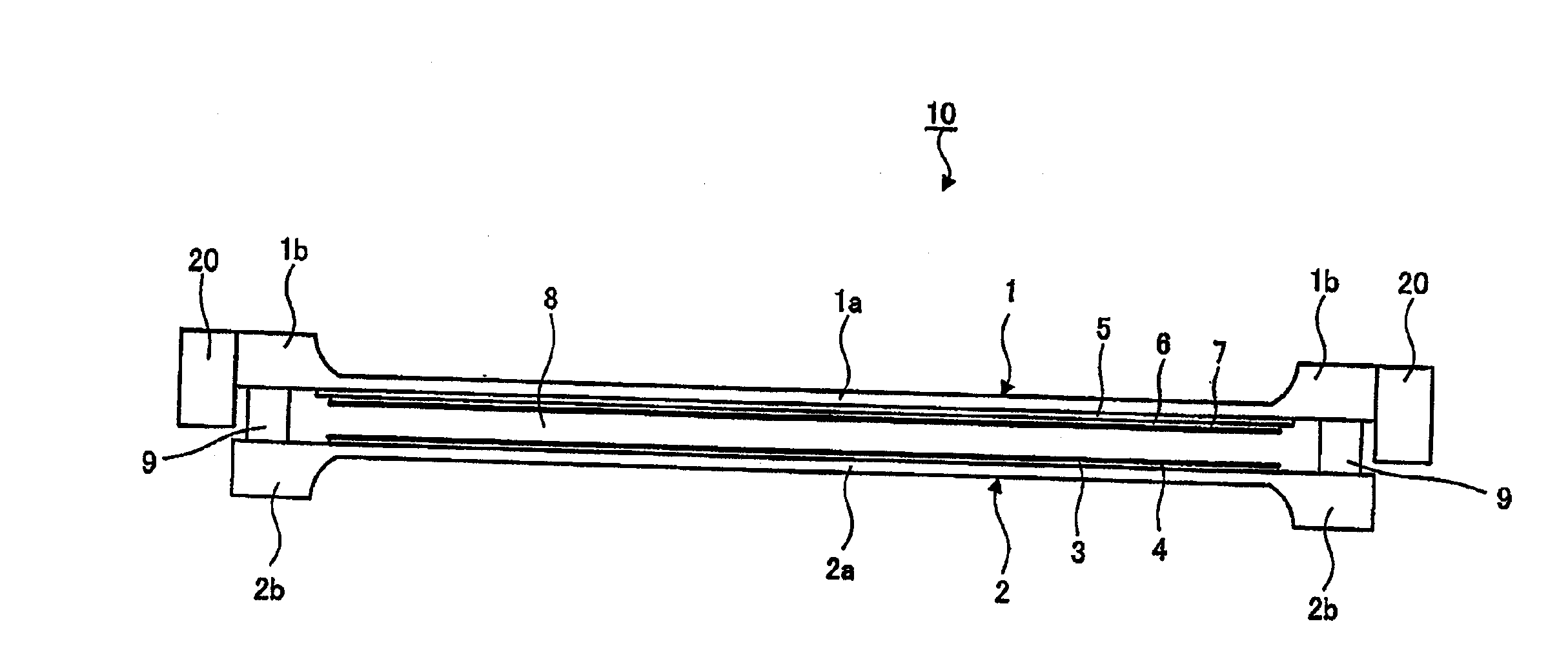
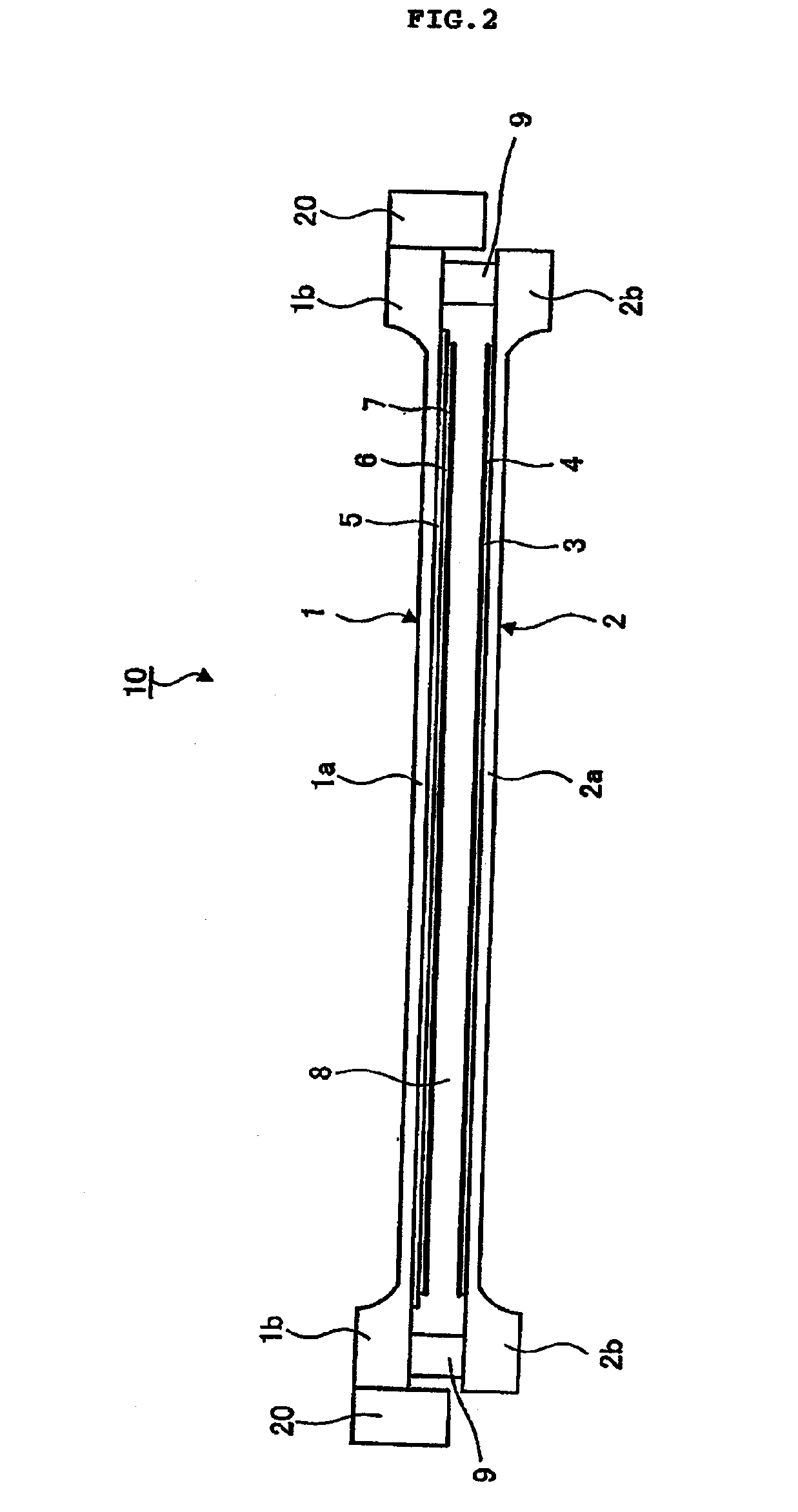
To provide a liquid crystal display device capable of outputting a sound of a sufficiently large volume by use of a liquid crystal cell which displays an image. A liquid crystal display device includes a thin front glass substrate having an outer surface in which a rib is formed on a peripheral portion, a back glass substrate arranged with a predetermined gap from an inner surface of the front glass substrate, in which liquid crystal is sealed in the gap, and a sound source element provided in contact with the front glass substrate.

Description

BACKGROUND OF THE INVENTION [0001] The present invention relates to a liquid crystal display device of a liquid crystal television set, a liquid crystal display for a cellular phone, and the like, which performs a display by modulating a linear polarization state, and more specifically, to a liquid crystal display device capable of outputting an audio from a screen itself. [0002] In recent years, liquid crystal display device technology, and particularly, liquid crystal display device technology using color display elements has significantly progressed. In the liquid crystal display device, downsizing / thinning, weight reduction, and further, lower power consumption, can be achieved. Accordingly, demand for liquid crystal display devices has rapidly expanded. Such a liquid crystal display device has a configuration in which an element (liquid crystal cell) formed by sandwiching a liquid crystal layer between a pair of glass substrates is provided, and polarizing plates are attached o...

Claims


Application Information

Patent Timeline
IPC IPC(8): G02F1/1333G02F1/13
CPCG02F1/1333
Inventor TSUBOI, KENJIMORIMOTO, TSUTOMU
Owner LINKEDIN
Learn More