Sensing device for measuring the three-dimension shape and its measuring method

a sensing device and three-dimensional shape technology, applied in the direction of measurement devices, instruments, using optical means, etc., can solve the problems of large measuring error, difficult to keep optical axes parallel, and the resolution of small shape changes at the hole or the edge is lower, so as to improve the measurement accuracy. the effect of greatly

Inactive Publication Date: 2005-08-11
LIU LANG
View PDF6 Cites 27 Cited by
  • Summary
  • Abstract
  • Description
  • Claims
  • Application Information

AI Technical Summary

Benefits of technology

[0010] Another purpose of this invention is to provide a method for 3-D object shape measurement by above-mentioned 3-D shape measurement sensing device. This method adopts cross optical axes, changes such operating distances as projected object distance and image distance, observed object distance and image distance to determine the objects of various sizes. Due to its accurate determination of the position of zero-order fringe, it can improve measurement accuracy greatly and achieve a high-precision whole-field measurement of object under the precondition of structured light rea...

Problems solved by technology

Parallel optical axes structure has following problems: (1) It is difficult to keep optical axes parallel; (2) the central parts of optical components of projector and camera are out of work, for the large aberration on their edges will bring about large measuring error.
However, because the high-frequency components are filtered with FFT, the r...

Method used


Image

  • Sensing device for measuring the three-dimension shape and its measuring method
  • Sensing device for measuring the three-dimension shape and its measuring method
  • Sensing device for measuring the three-dimension shape and its measuring method

Examples


embodiment 1

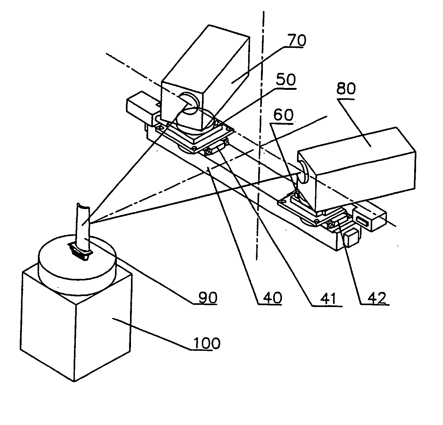
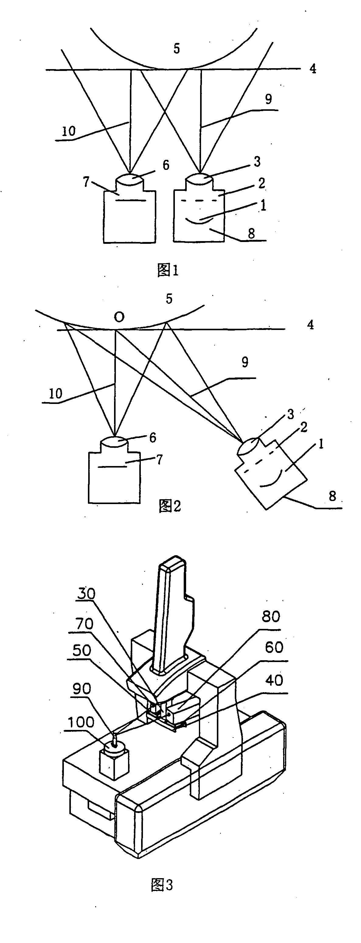
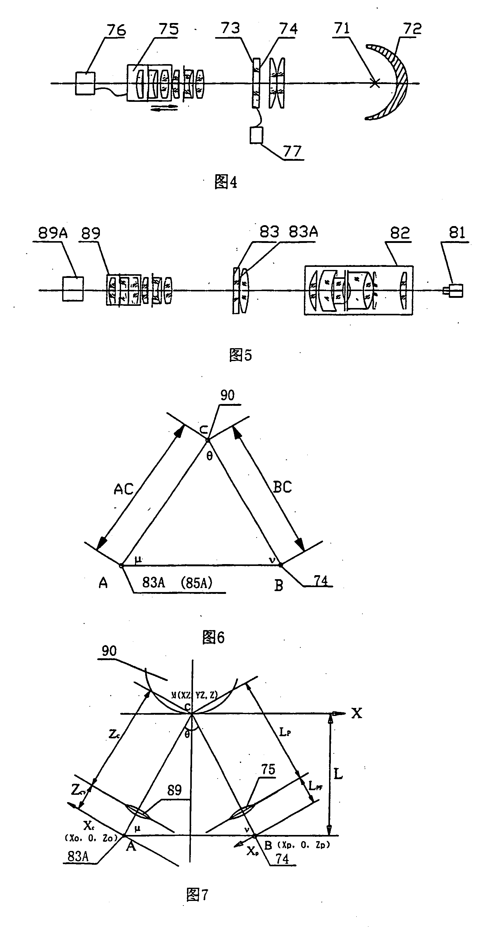
[0094] See Charts 3 and 15. Install projection device 70 on projection slider 41 of rectilinear motion axis 40 with grating ruler and double sliders. Install observation device 80 on observation slider 42 of rectilinear motion axis 40 with double sliders. The rectilinear motion axis 40 with double sliders is hung on three-coordinates moving arm 30 that can do three-dimensional movement, and keeps vertical to Z shaft of three-coordinates moving arm. The optical centers of observation device 80 and projection device 70 are at a same level, the to-be-measured object is installed on the rotary positioning table which can do 360° rotation (German PI Company's rotary positioner M039). Projection device 70 joins with power supply by cable. The observation camera 81 and observation camera 88 of observation device 80 joins with Matrox Pulser 4-channel image capture board by cable (not showed in the Chart), and the image capture board is plugged in computer (not showed in the Chart). The proj...

embodiment 2

[0098] Refer to Chart 3. The sensing device can be installed on three-coordinates moving arm, like that in Chart 10. The projection rotary positioning table 50 adopts German PI Company's rotary positioner M039, installed on rectilinear motion axis 40. The observation rotary positioning table 60 adopts German PI Company's rotary positioner M039, installed on rectilinear motion axis 40. Projection device 70 is installed on projection rotary positioning table 50 and observation device 80 is installed on observation rotary positioning table 60. The mark point 73 of projection device 70 coincides with the rotating center of projection rotary positioning table 50, and the mark point 83A of observation device 80 coincides with the rotating center of rotary positioning table 60. The optical axis of observation device 80 and rectilinear motion axis 40 are crossed as a μ angle, the optical axis of projection device 70 and rectilinear motion axis 40 are crossed as a ν angle, and the optical ax...

embodiment 3

[0103] Refer to Chart 3. The sensing device can be installed on three-coordiniates moving arm, like that in Chart 9. Projecting positioner and observing positioner are equipped with projection slider 41, observation slider 42 and rectilinear motion axis 40. In such case, the said projection slider 41 has a projection rotary positioning table 50 on it, which adopts German PI Company's rotary positioner M039, and the observation slider 42 has an observation, rotary positioning table 60, which adopts German PI Company's rotary positioner M039. Projection device 70 (see Chart 11) is installed on projection rotary positioning table 50, and observation device 80 (see Chart 5) is installed on observation rotary positioning table 60. Utilize projection rotary positioning table 50 and / or observation rotary positioning table 60 and movement of sliders, drive respectively the movement or rotation of projection device 70 and / or observation device 80, so as to enable the optical axes of projecti...


PUM


Abstract

The present invention discloses a sensing device for measuring the three dimension shape and its measuring method. The said sensing device includes a projecting device, an observing device, a projecting localizer, an observing localizer and a computer for data processing. The optic axis of the projecting device and the optic axis of the observing device are crossed on the surface of the object by the relative motion and the focusing of the projecting device and the observing device, such that the viewing field of the whole field measurement and the position of the zero-order fringe are determined. The projecting device and the observing device are focused automatically by means of the object distance and the image distance of the projecting device in this viewing field, and the object distance and the image distance of the observing device in this viewing field. The camera in the observing device records the fringe patterns respectively after phase shifting and the computer calculates the three dimension surface shape of the object. The present invention achieves whole-field high accuracy and high speed absolute measurement of the three dimension object shape in the variable viewing field.

Description

TECHNOLOGICAL FIELD [0001] This invention is about a kind of sensing device for 3-D shape measurement and its measuring method, in particular, a sensing device for absolute measurement of object 3-D shape with structured light and its measuring method. BACKGROUND TECHNOLOGY [0002] The structured light 3-D shape measurement is a kind of technique available for whole-field measurement of object shape. It can adopt parallel optical axes structure or cross-optical axes structure. The structured light in question includes projected grating and projected moire. These two are often used as the same owing to indefinite difference other than the quantity of gratings between them. [0003] Takade and other persons publish the “Fourier Transform Profilometry For The Automatic Measurement Of 3-D Object Shapes” on Applied Optics (vol.22, No.24, Dec. 15, 1983,P3977-3982), and Opton Company shows these two structures in the Moiré Report issued on its website. Drawing 1 is sketch of parallel optical ...

Claims


Application Information

Patent Timeline
IPC IPC(8): G01B11/24G01B11/25
CPCG01B11/25G01B11/2441
Inventor LIU, LANG
Owner LIU LANG
Why Eureka
Try Eureka