
Magnetic recording head, magnetic reproducing head, magnetic head, tape drive and disk drive

a technology of reproducing head and magnetic head, which is applied in the direction of recording information storage, track selection/addressing details, instruments, etc., can solve the problems of limiting the positioning accuracy of each masking in the lamination, the difference between the top and bottom magnetic head elements in the width direction of the head, and the significant difference between the top and bottom magnetic head elements in the lamination direction, so as to simplify the manufacturing process. , the effect of simplifying the manufacturing process

Inactive Publication Date: 2005-08-11
SONY CORP
View PDF10 Cites 6 Cited by
  • Summary
  • Abstract
  • Description
  • Claims
  • Application Information

AI Technical Summary

Benefits of technology

[0017] As a result, there is a limit to the number of laminations allowable for the magnetic head layers, thereby preventing the multi-channeling, and in consequence, the higher recording density and reproducing of information.
[0036] In other words, as environmental conditions such as temperature at the time of manufacture of the magnetic recording head layer or of the magnetic reproducing head layer differ, if it is arranged so as to change the environment after completion of the manufacture of the magnetic recording head layer for a subsequent manufacture of the magnetic reproducing head layer, an alteration cycle of the process environment can be reduced to once, thereby substantially simplifying the manufacturing process.

Problems solved by technology

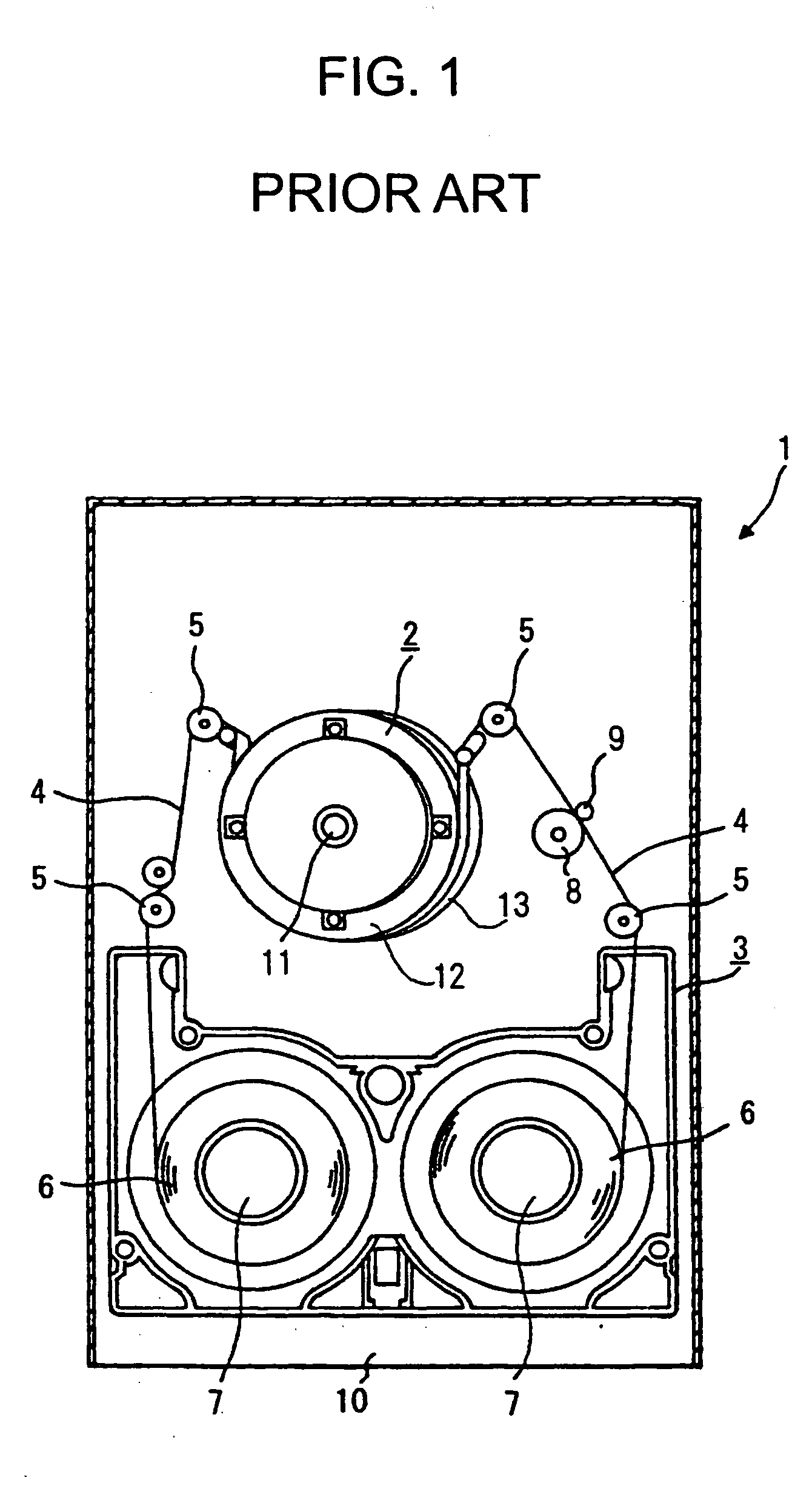
However, when a plurality of magnetic head layers are laminated, there occurs a problem that, due to an error in accuracy of positioning (alignment error) between each magnetic head element in its width direction, a displacement between the top magnetic head element and the bottom magnetic head element in the head width direction becomes considerably large.
This is caused by the fact that, when forming magnetic head elements by a thin film processing, each layer thereof is formed by masking with a mask and depositing a film, however, there is a limit to securing accuracy in positioning of each masking in the lamination.

Method used


Image

  • Magnetic recording head, magnetic reproducing head, magnetic head, tape drive and disk drive
  • Magnetic recording head, magnetic reproducing head, magnetic head, tape drive and disk drive
  • Magnetic recording head, magnetic reproducing head, magnetic head, tape drive and disk drive

Examples


first embodiment

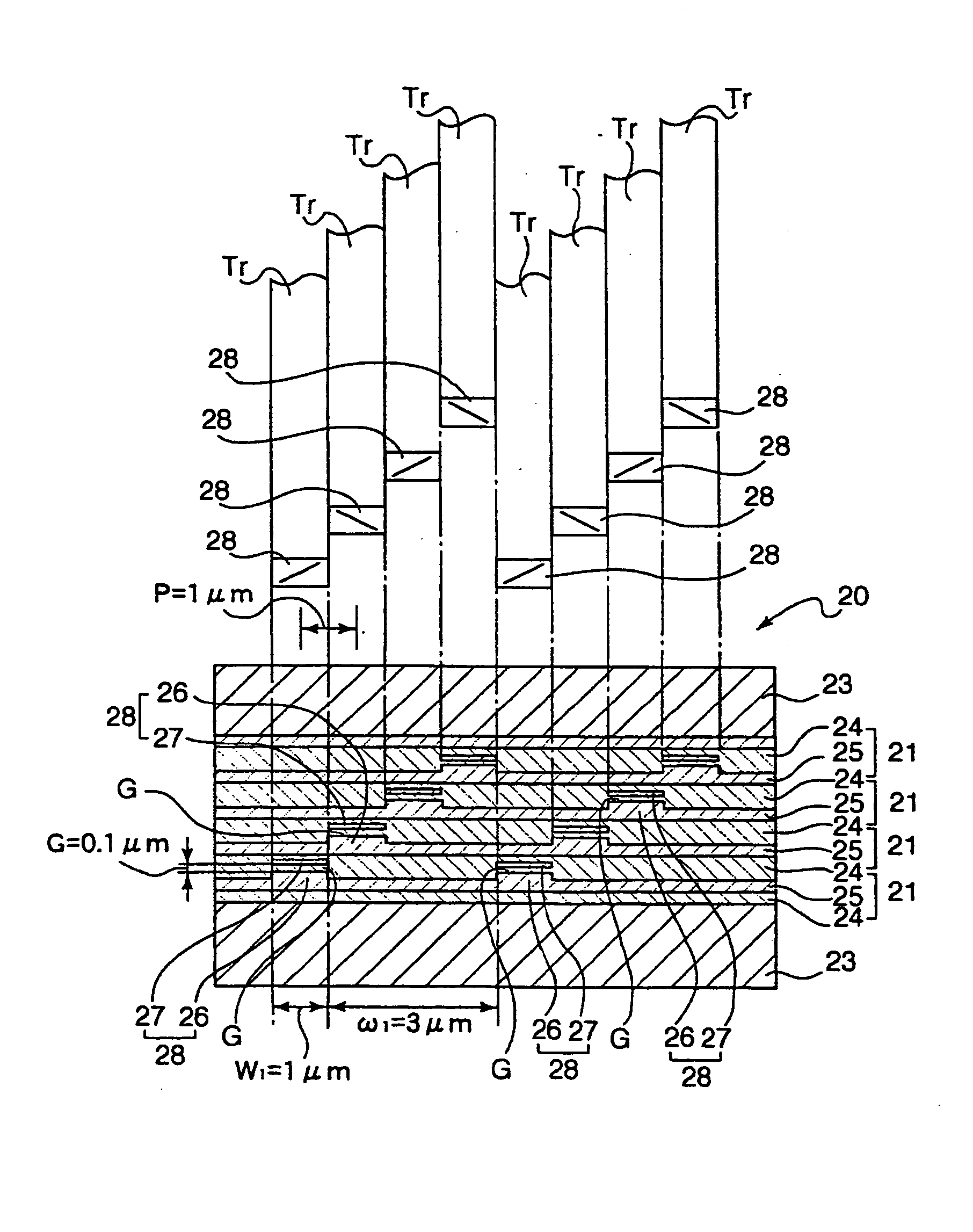
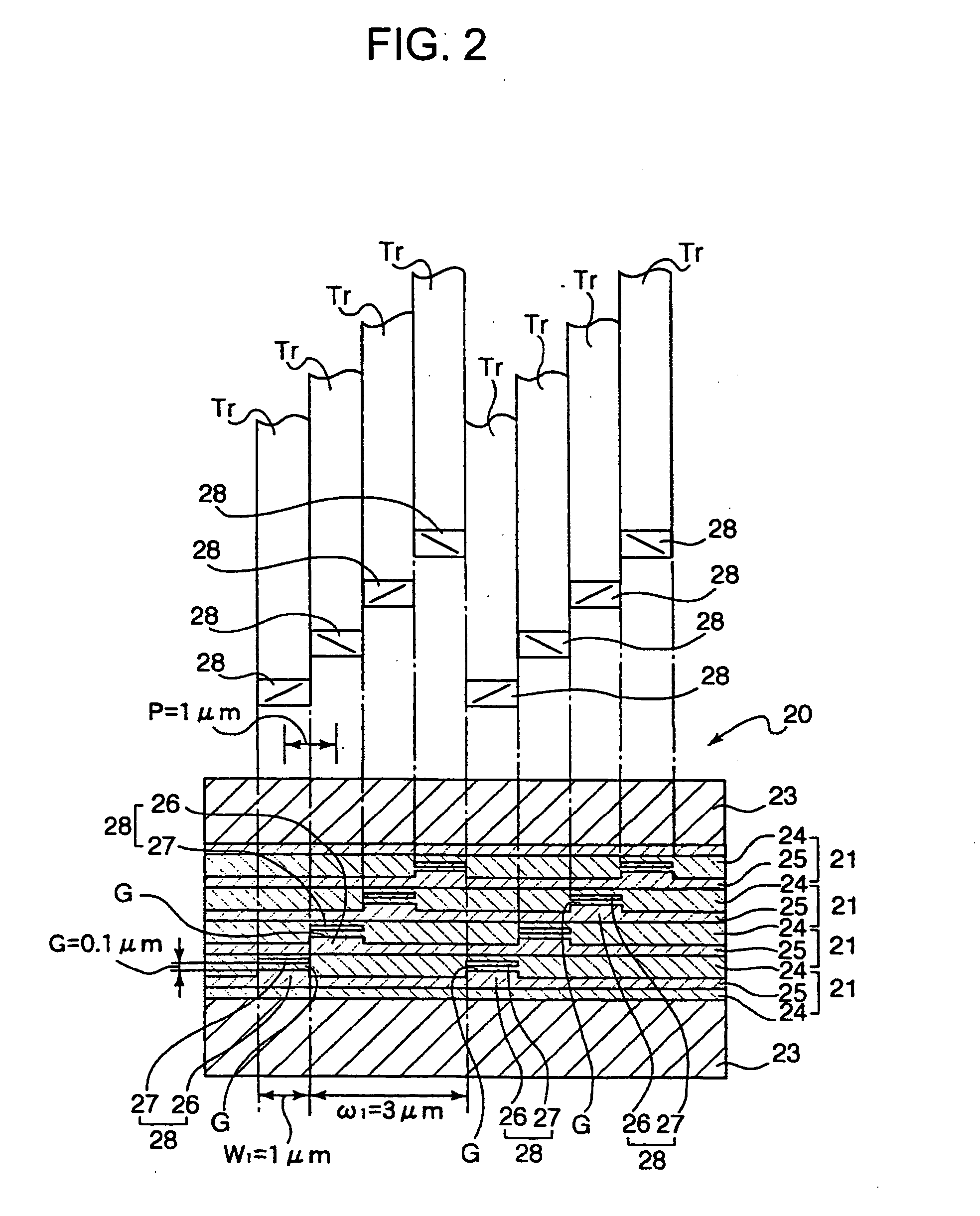
[0070] In one magnetic recording head layer 21 there are disposed two magnetic recording head elements 28, 28 separated by a predetermined distance from each other in the direction of the head width thereof. As a result, the magnetic recording head 20 thus assembled according to the present invention has eight pieces of the magnetic recording head elements 28, 28, . . . , 28 in total, as illustrated in FIG. 2.

[0071] Any two magnetic recording head elements 28, 28 adjacent in the direction of lamination via an insulating layer 24 are made share one common layer of insulating layer 24. As a result, the magnetic recording head 20 is composed by alternately laminating five layers of insulating layers 24, 24, . . . , 24 and four layers of magnetic film layers 25, 25, . . . , 25 between the bottom non-magnetic substrate 22 and the upper non-magnetic substrate 23, more specifically such as “the bottom nonmagnetic substrate 22-insulating layer 24-magnetic film layer 25-insulating layer 24-m...

second embodiment

[0095] Also, in the magnetic recording head 20A according to this second embodiment of the present invention, likewise the case of the magnetic recording head 20 according to the first preferred embodiment, because that a width of each of the magnetic recording head elements 28A, 28A, . . . can be reduced and that an alignment error between each of the magnetic recording head elements 28A, 28A, . . . can be minimized, narrower recording tracks with higher density can be formed, thereby permitting realizing a magnetic recording head 20A able to respond to increasing multi-channeling.

[0096] A third exemplary preferred embodiment of the present invention is shown in FIGS. 8 to 10, as applied to a magnetic reproducing head having eight pieces of magneto-resistive effect thin film heads (hereinafter referred to as MR head).

[0097] It should be noted that the arrangement of MR heads in a magnetic reproducing head 40 according to this third preferred embodiment of the present invention is ...


PUM

PropertyMeasurementUnit
widthaaaaaaaaaa
widthaaaaaaaaaa
recording densityaaaaaaaaaa

Abstract

A magnetic recording / reproducing head having a plurality of magnetic head elements for multi-channeling capable of achieving high density recording / reproducing capability, including: a plurality of magnetic recording / reproducing head layers each including magnetic recording / reproducing head elements fabricated by a thin film process and interposed between two insulating / magnetic shielding layers laminated on a non-magnetic substrate; the total of magnetic recording / reproducing head elements formed therein are displaced from each other in a head width direction, and each magnetic recording / reproducing head layer has a plurality of magnetic recording / reproducing head elements formed at a predetermined pitch.

Description

CROSS REFERENCE TO RELATED APPLICATIONS [0001] The present document is based on Japanese Priority Application JP2002-140556, filed in the Japanese Patent Office on May 15, 2002, the contents of which being incorporated herein by reference to the extent permitted by law. BACKGROUND OF THE INVENTION [0002] 1. Field of the Invention [0003] The present invention relates to a magnetic recording head, a magnetic reproducing head, a magnetic head, a tape drive and a disk drive using a similar, and in particular, relates to a technology for facilitating arrangement of a plurality of magnetic heads (including both magnetic recording heads and magnetic reproducing heads) (hereinafter referred to as multiplicity of magnetic heads) in order to achieve higher recording density. [0004] 2. Description of the Related Art [0005] Recently, in order to realize large capacity of storage for magnetic recording media, an increasingly higher recording density is required for magnetic heads, so that the us...

Claims


Application Information

Patent Timeline
Patent Type & Authority Applications(United States)
IPC IPC(8): G11B5/115G11B5/29G11B5/31G11B5/39G11B5/48G11B5/49G11B5/53
CPCG11B5/115G11B5/534G11B5/3103G11B5/3116G11B5/3163G11B5/3903G11B5/3912G11B5/3951G11B5/3967G11B5/488G11B5/4886G11B5/4893G11B5/4976G11B5/531G11B5/295
Inventor OZUE, TADASHISODA, YUTAKA
Owner SONY CORP
Learn More