Equalizer status monitor

a status monitor and equalizer technology, applied in the field of equalizers, can solve the problems of unusable and often undetectable output of other monitoring schemes, unreasonably high snr, and rapid increment of error counters, and achieve the effect of simplifying test logic criteria and reducing the complexity of associated hardwar

Inactive Publication Date: 2005-08-11
THOMSON LICENSING SA
View PDF20 Cites 153 Cited by
  • Summary
  • Abstract
  • Description
  • Claims
  • Application Information

AI Technical Summary

Benefits of technology

[0015] The present invention addresses the problem of reliably detecting a divergent or unstable adaptive equalizer when used to recover data from modulated signals. The monitor of the present invention collects data samples from the output signal of the adaptive equalizer. The data is then sent to a slicer. A memory associated with the monitor contains a...

Problems solved by technology

For most realistic communication channel conditions, the lack of an initial signal estimate results in high decision error rates, which cause the successively calculated equalizer filter parameters to continue to fluctuate, rather than converge to a desired solution.
When the equalizer is in such a divergent state, its output is both unusable and often un...

Method used


Image

  • Equalizer status monitor
  • Equalizer status monitor
  • Equalizer status monitor

Examples


Embodiment Construction

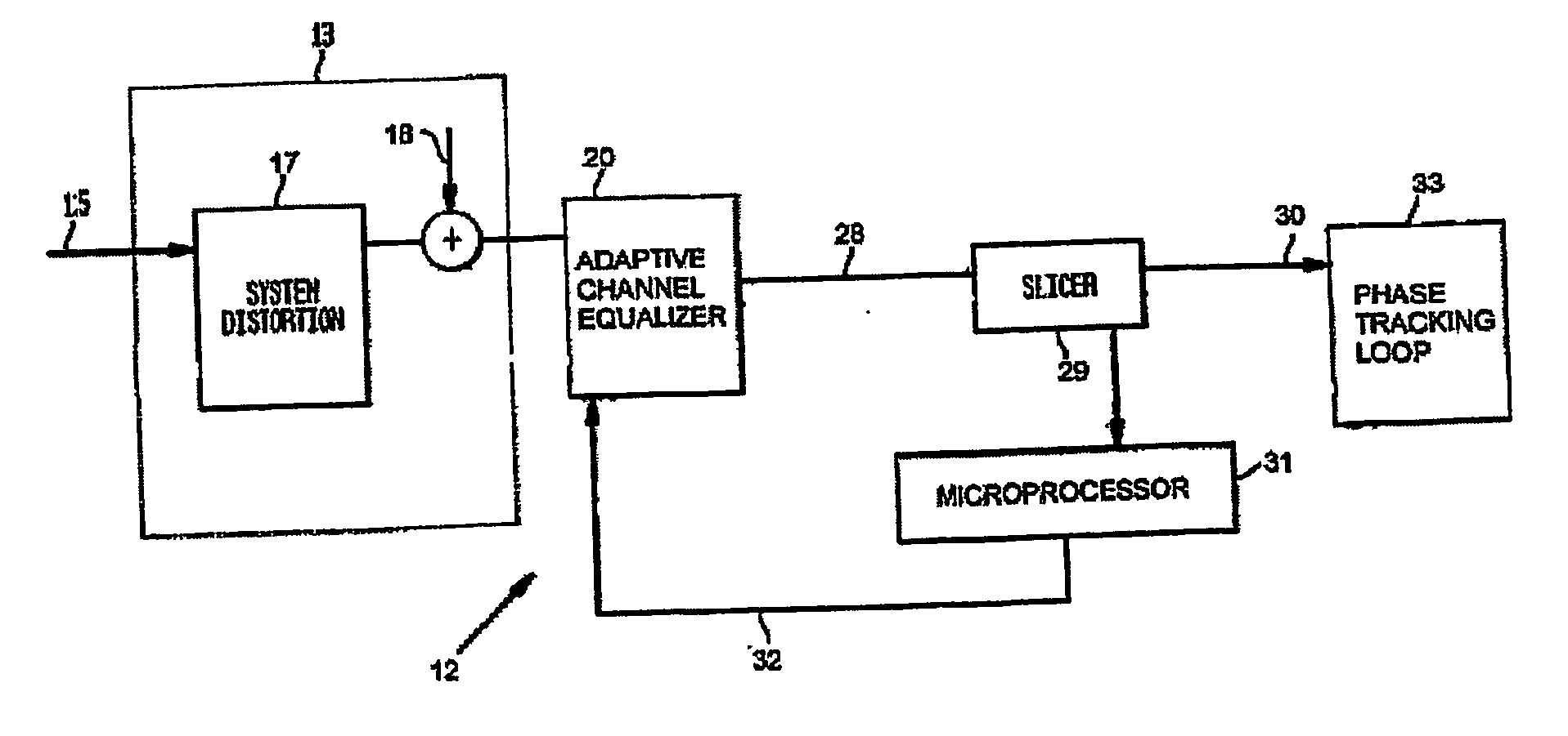
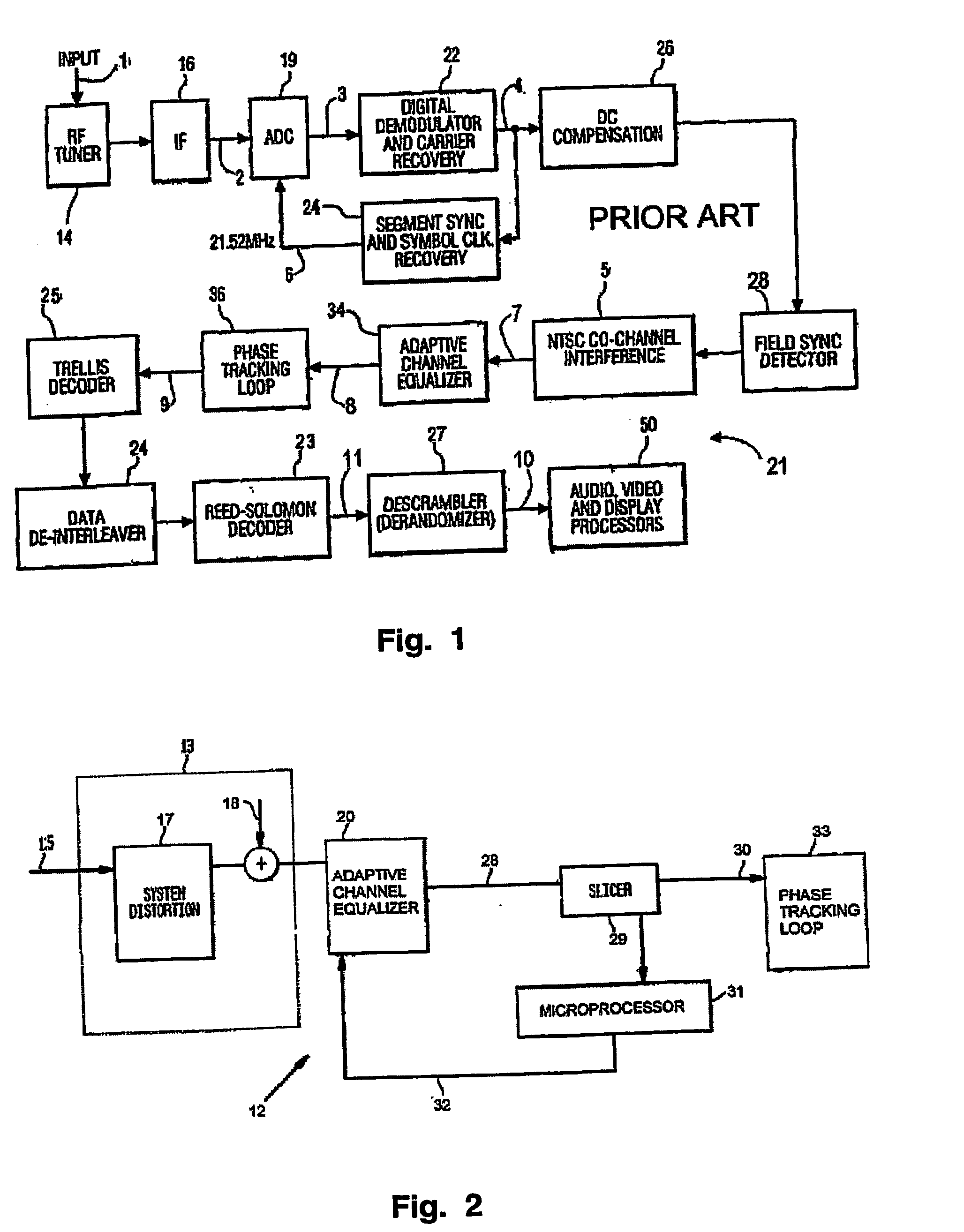
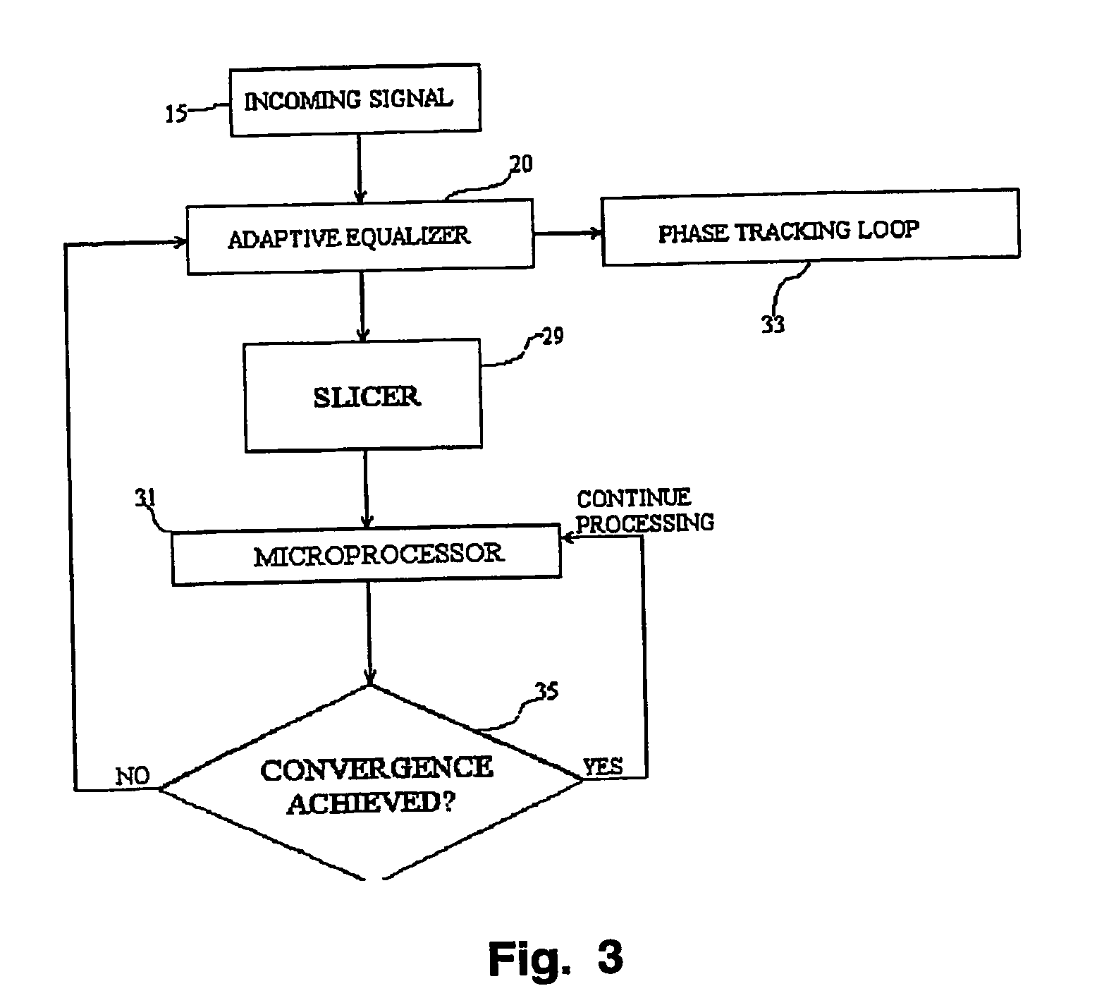
[0019]FIG. 2 depicts a portion of an HDTV receiver 12, and FIG. 3 illustrates a data flow chart, corresponding to FIG. 2, illustrating the flow of data through the system of FIG. 2. Corresponding elements in FIGS. 2 and 3 are designated by the same reference numbers, and will be discussed together below. The input signal 15 is received from a previous stage of the HDTV receiver such as an NTSC co-channel interference rejection network. The overall communication channel 13 introduces system distortion 17 and noise 18 into the signal 15. Referring to FIG. 3, the received signal 15 is the input to the adaptive channel equalizer 20, which is typically implemented as an infinite impulse response filter. The output 28 of the equalizer 20 is the input signal to the slicer 29, the slicer being a ‘nearest element’ decision device. The slicer 29 is responsive to the signal 28 at its input, and its output 30 is the projection of the nearest symbol value residing within the grid of constellatio...


PUM


Abstract

A system for monitoring the output of an adaptive channel equalizer in order to determine if convergence has been achieved. A slicer samples data from the equalizer during a predetermined period. The output data from the slicer is forwarded to a microprocessor in order to apply a test standard to the slicer data. For example, if one of every possible transmitted symbol is detected by the microprocessor, convergence is assumed to have occurred. If the test criterion is not met, a reset signal is sent to the equalizer.

Description

[0001] The present patent application is based on and claims priority from Provisional U.S. Patent Application No. 60 / 373,155 of the same title filed on Apr. 17, 2002.BACKGROUND [0002] 1. Field of the Invention [0003] This invention relates to generally to an equalizer for use in receiving digital communications signals, and more particularly to adaptive channel equalization of an image representative signal which may be processed by a High Definition Television (HDTV) receiver. [0004] 2. Background [0005] An example of a portion of a prior art HDTV system 21 is depicted in FIG. 1. In such a system, a terrestrial broadcast signal 1 is forwarded to an input network that includes an RF tuning circuit 14 and an intermediate frequency processor 16 for producing an IF passband output signal 2. The broadcast signal 1 is a carrier suppressed eight bit vestigial sideband (VSB) modulated signal as specified by the Grand Alliance for HDTV standards. Such a VSB signal is represented by a one d...

Claims


Application Information

Patent Timeline
IPC IPC(8): H03K5/159H04L27/01H04B3/06H04B7/005H04L25/03H04N5/21H04N17/00
CPCH04L25/03019H04L25/03025H04N17/004H04L2025/037H04N5/211H04L2025/03382H04N7/015H04N7/12
Inventor BOUILLETT, AARON REEL
Owner THOMSON LICENSING SA
Why Eureka
Try Eureka