Pre-connectorized fiber optic distribution cable

a fiber optic distribution cable and pre-connector technology, applied in the direction of optics, fibre mechanical structures, instruments, etc., can solve the problems of affecting the use of the assembled cable, hindering the winding of the assembled cable onto the cable reel, and a high cost of a highly skilled field technician, so as to achieve convenient deployment, short length of optical fibers, and low profile mid-span access

Inactive Publication Date: 2005-08-11
CORNING CABLE SYST LLC
View PDF10 Cites 118 Cited by
  • Summary
  • Abstract
  • Description
  • Claims
  • Application Information

AI Technical Summary

Benefits of technology

[0009] To achieve the foregoing and other objects, and in accordance with the purposes of the invention as embodied and broadly described herein, the present invention provides various embodiments of a factory assembled, pre-connectorized fiber optic distribution cable having at least one predetermined access location for providing access to at least one preterminated and pre-connectorized optical fiber. The factory pre-connectorized distribution cable may be wound upon a cable reel and installed through a conduit having a diameter of less than about 1.9 inches. A particular advantage of this pre-connectorized distribution cable over conventional cable systems is the ability to readily connect pre-connectorized drop cables without fusion splicing in the field, which reduces labor time and cost, and lends itself to installation flexibility. Each access location has an outer diameter of less than about 1.9 inches, and more preferably, less than about 1.5 inches, and presents at least one pre-connectorized optical fiber at the access location for readily connecting at least one drop cable to the distribution cable after installation. Another advantage of the present invention is the ability to utilize a variety of different closure designs to protect the factory prepared splices and connectors, and to anchor the drop cables.
[0010] In one embodiment, the pre-connectorized fiber optic distribution cable comprises any fiber optic cable having at least one optical fiber disposed within a tubular body, wherein the tubular body may include, but is not limited to, a buffer tube, a monotube or a tube formed from a water-swellable tape. In order to achieve a low profile mid-span access, a section of the cable sheath is removed in the factory to expose the tubular body within the distribution cable. For each access location, the appropriate tubular body may be accessed at one or more places along the exposed section of the tubular body. In embodiments in which the tubular body is a buffer tube, a known fiber access tool may be used to penetrate the buffer tube in at least two locations. Starting at the appropriate access point, pre-selected optical fibers are accessed and severed. The remaining optical fibers remain intact and continue along the distribution cable. In embodiments in which the distribution cable comprises a plurality of individual optical fibers, the pre-selected optical fibers may be fished out of a second access point in the tubular body to thereby expose short lengths of the optical fibers. In embodiments in which the distribution cable comprises ribbonized fibers (i.e., one or more fiber ribbons), a larger portion of the tubular body, and typically the entire portion of the tubular body within the removed section of the cable sheath, may be opened in order to sever and separate a number of pre-selected optical fibers from the ribbon.
[0011] In either case, the preterminated optical fibers may be routed through a transition piece and guided into one or more protective tubes secured to the transition piece. The transition piece may be secured to a structural member (e.g., a strength member) of the cable or to the tubular body at the location where the optical fibers ultimately exit the tubular body. The transition piece is thereby secured against torque and may help seal the optical fiber exit point. The preterminated optical fibers are spliced in the factory to tight buffered or jacketed connectorized optical fibers, (i.e., pigtails), so as to provide a total pre-connectorized fiber length of at least about 20 inches. The access points on the tubular body may be sealed using a heat shrinkable material, tubing or a self-fusing or self-amalgamating tape. A plurality of cable centralizers are positioned at various intervals along the length of the access location. The cable centralizers are operable for centering the distribution cable within a protective shell and for routing and protecting the pre-connectorized optical fibers. In one embodiment, the protective shell is overmolded over the entire access location. In an alternative embodiment, the protective shell is threaded onto the distribution cable, positioned over the entire access location and secured. Diameter transition members are used to provide a smooth transition between the outer diameter of the distribution cable and the outer diameter of the protective shell. End caps provide axial and torsional resistance to the assembly. Heat shrinkable material with at least one ripcord disposed underneath is positioned over the diameter transition members, end caps and a portion of the protective shell. Once the distribution cable is installed, the at least one ripcord may be used to remove the heat shrinkable material and protective shell in order to expose the pre-connectorized optical fibers. In preferred embodiments, all components of the access location are designed such that they can be positioned on the distribution cable without having to feed the components along the entire length of the distribution cable.
[0012] In another embodiment, the present invention provides a pre-connectorized fiber optic distribution cable for use in an optical network. The pre-connectorized distribution cable comprises a plurality of predetermined mid-span access locations along the cable length. The pre-connectorized distribution cable may be readily deployed in an optical network in an assembled and protected configuration, and the protective components may be easily removed in the field and a closure added to the distribution cable to conceal and protect each predetermined access location. In one embodiment, the pre-connectorized optical fibers may be connected inside the enclosure to an adapter or receptacle provided in a connector port of the closure. A pre-connectorized drop cable from the optical network may then be readily connected to the pre-connectorized optical fiber within the connector port.
[0013] In a further embodiment, the present invention provides a method of mid-span accessing a fiber optic distribution cable at a predetermined access location to connectorize at least one optical fiber. The method comprises: (1) removing a length of the cable sheath to expose a predetermined length of at least one tubular body; (2) making a first cut on the appropriate tubular body; (3) severing one or more pre-selected optical fibers at the location of the first cut; (4) making a second cut on the appropriate tubular body about 9 to 12 inches upstream from the first cut; (5) fishing the pre-selected and severed optical fibers out of the second cut to present an optical fiber length of about 9 to 15 inches; (6) repairing the first cut point; and (8) splicing a pigtail to the optical fiber length to provide a preterminated and pre-connectorized optical fiber having a length of at least about 20 inches.
[0014] In a still further embodiment, the present invention provides a method of mid-span accessing a fiber optic distribution cable at a predetermined access location to connectorize at least one optical fiber of a fiber ribbon. The method comprises: (1) removing a length of a cable sheath to expose a predetermined length of at least one tubular body; (2) opening a predetermined length of the at least one tubular body to expose a plurality of ribbon optical fibers; (3) severing pre-selected optical fibers; (4) separating the pre-selected and severed optical fibers from the ribbon to present a predetermined fiber length; (5) splicing a pigtail to each optical fiber; and (6) covering and protecting the uncut ribbon fibers.

Problems solved by technology

This time consuming process is typically accomplished by a highly skilled field technician at a significant cost and under field working conditions.
While the preterminated fiber optic cable assembly described in the Nilsson et al. patent is useful in certain applications, its use is limited to applications in which it is installed through a conduit having an outer diameter of about 4 inches or greater.
In addition, the relatively large outer diameter of the splice closure greatly hinders winding the assembled cable onto a cable reel.
A disadvantage of this system is that the outer diameter of the assembly exceeds the inner diameter of the conduit through which the cable system is typically installed within when multiple drop cables are connected at a single branch point.

Method used


Image

  • Pre-connectorized fiber optic distribution cable
  • Pre-connectorized fiber optic distribution cable
  • Pre-connectorized fiber optic distribution cable

Examples


Embodiment Construction

[0026] The present invention will now be described more fully hereinafter with reference to the accompanying drawings in which exemplary embodiments of the invention are shown. However, this invention may be embodied in many different forms and should not be construed as limited to the embodiments set forth herein. These exemplary embodiments are provided so that this disclosure will be both thorough and complete, and will fully convey the scope of the invention to those skilled in the art. Like reference numbers refer to like elements throughout the various drawings.

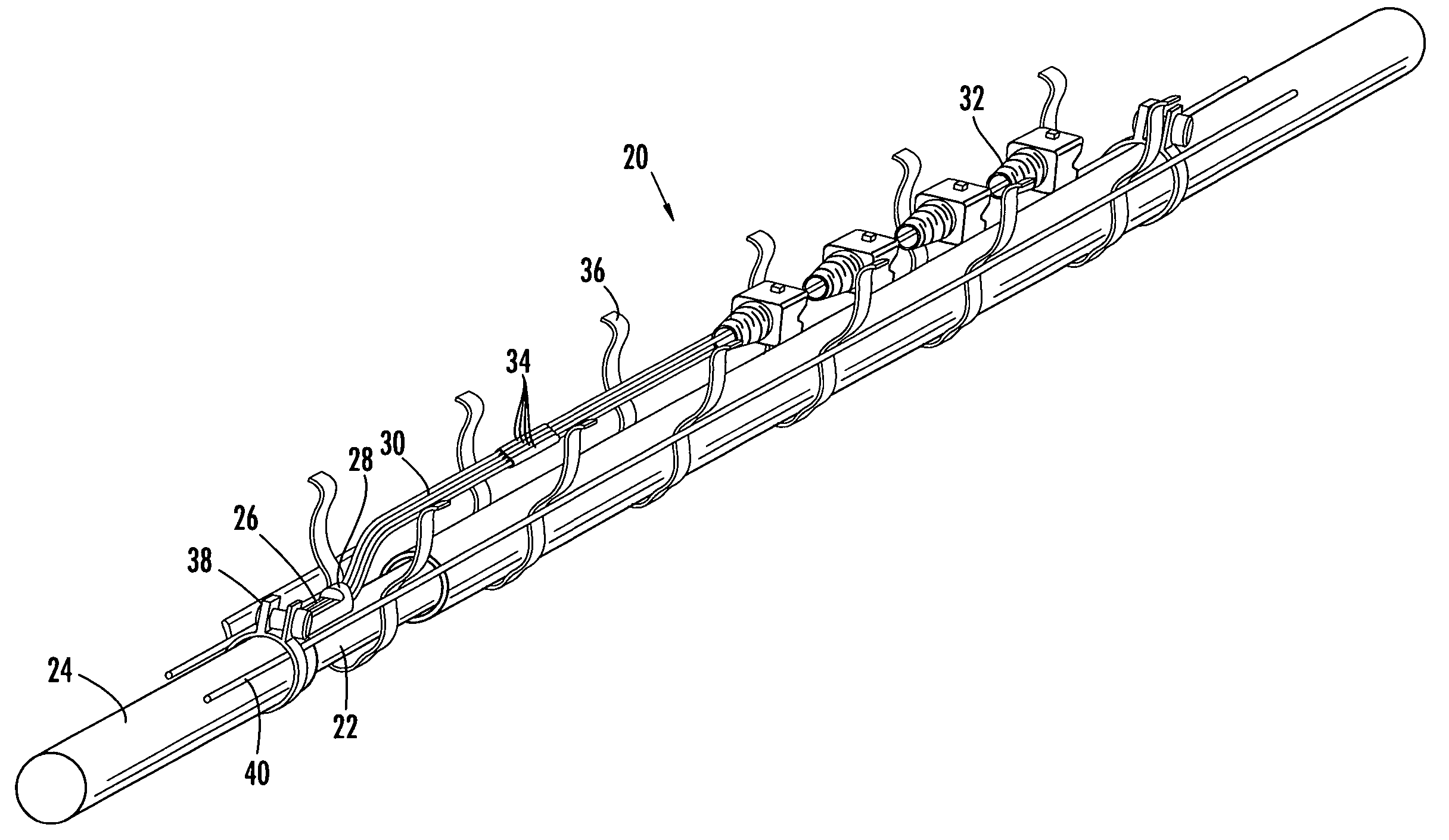
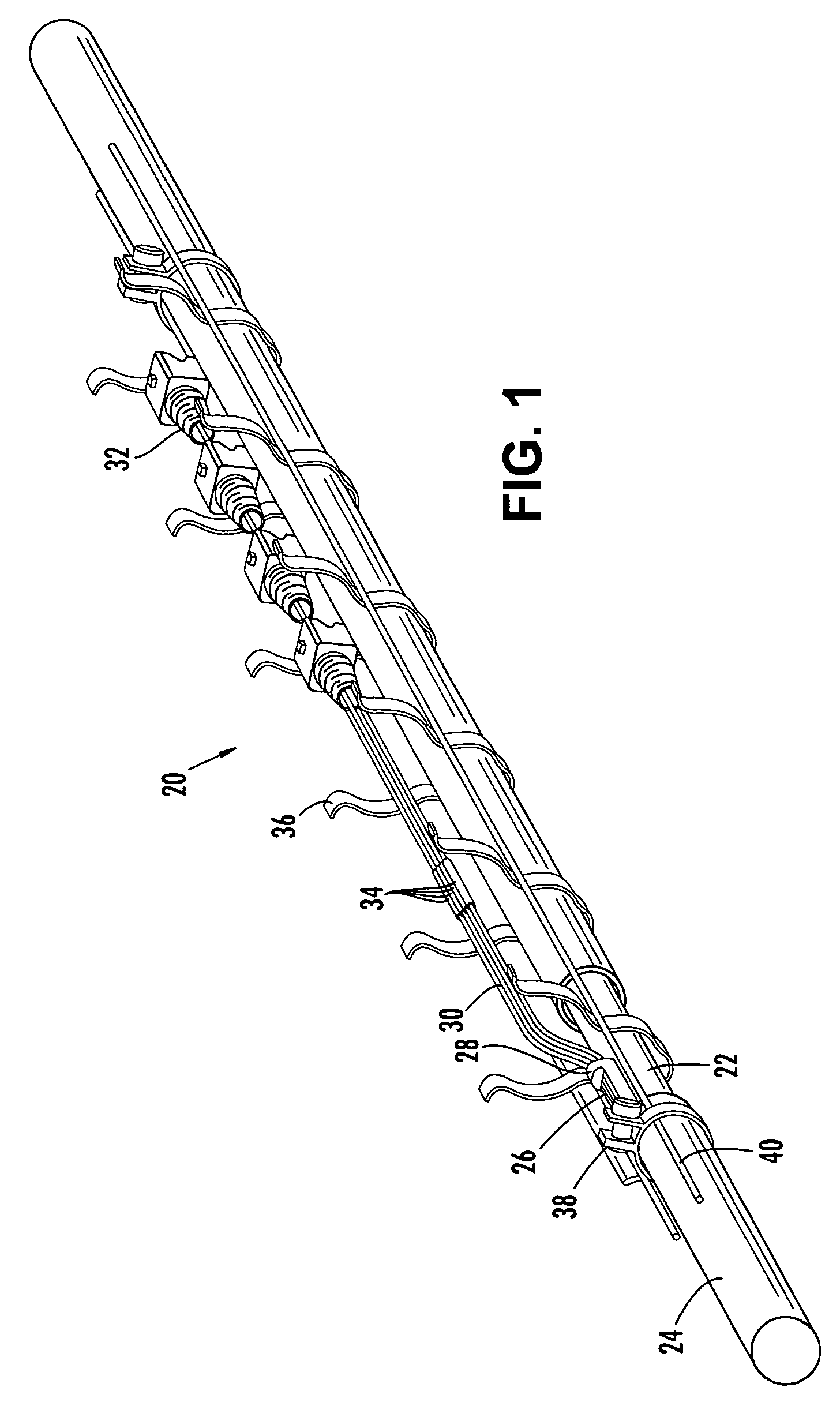
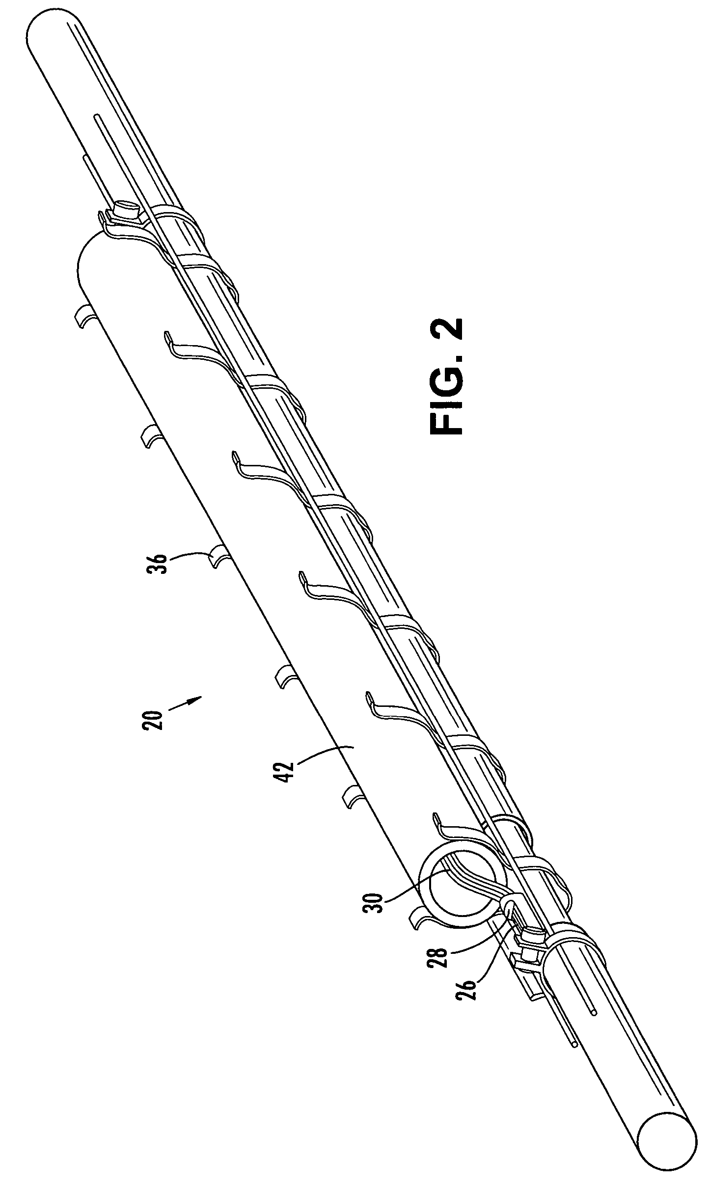
[0027] The pre-connectorized fiber optic distribution cable of the present invention comprises at least one predetermined access location along the cable length for providing access to at least one preterminated and pre-connectorized optical fiber. In preferred embodiments, the pre-connectorized distribution cable comprises a plurality of access locations at spaced apart locations along the cable length, thus providing...


PUM


Abstract

A factory prepared fiber optic distribution cable has at least one predetermined access location for providing access to at least one pre-connectorized optical fiber. The fiber optic distribution cable includes at least one preterminated optical fiber withdrawn from a tubular body at the access location, a connector attached to the preterminated optical fiber, a transition piece for transitioning the preterminated optical fiber from the tubular body into a protective tube, and a protective shell encapsulating the access location for protecting the pre-connectorized optical fiber. Alternatively, the fiber optic distribution cable includes at least one preterminated optical fiber withdrawn from a tubular body, a transition piece for transitioning the preterminated optical fiber from the tubular body into a protective tube, a connector attached to the preterminated optical fiber, a plurality of cable centralizers, and a protective shell for encapsulating the access location and protecting the pre-connectorized optical fiber.

Description

BACKGROUND OF THE INVENTION [0001] 1. Field of the Invention [0002] The present invention relates generally to a fiber optic distribution cable and, more particularly, to a factory assembled fiber optic distribution cable having at least one predetermined access location for providing access to at least one preterminated and pre-connectorized optical fiber. [0003] 2. Description of the Related Art [0004] Optical fibers are used for a variety of applications including voice communication, data transmission and the like. With the ever-increasing need for connecting remote locations to a fiber optic distribution cable, it is apparent that more efficient methods of performing a mid-span access of a distribution cable are required. Typically, to perform a mid-span access, a technician must remove a portion of the cable sheath in the field at a convenient location along an installed distribution cable. Once the sheath is removed, the technician must access pre-selected optical fibers, sev...

Claims


Application Information

Patent Timeline
Patent Type & Authority Applications(United States)
IPC IPC(8): G02B6/44
CPCG02B6/4472G02B6/4495G02B6/4475G02B6/4431
Inventor ELKINS, ROBERT B. IICOOKE, TERRY L.JOHNSON, JOHN B.KNECHT, DENNIS M.LUTHER, JAMES P.NIELSEN, LARS K.
Owner CORNING CABLE SYST LLC
Why Eureka
Try Eureka