
Hermetic compressor

a compressor and hermetic technology, applied in the direction of liquid fuel engines, positive displacement liquid engines, lighting and heating apparatus, etc., can solve the problems of compressor damage, lubrication malfunction, and low so as to reduce the viscosity of lubricant oil, reduce the pressure of lubricant oil, and reduce the dissolubility of refrigerant to lubricant oil.

Inactive Publication Date: 2005-08-11
DAIKIN IND LTD
View PDF5 Cites 9 Cited by
  • Summary
  • Abstract
  • Description
  • Claims
  • Application Information

AI Technical Summary

Benefits of technology

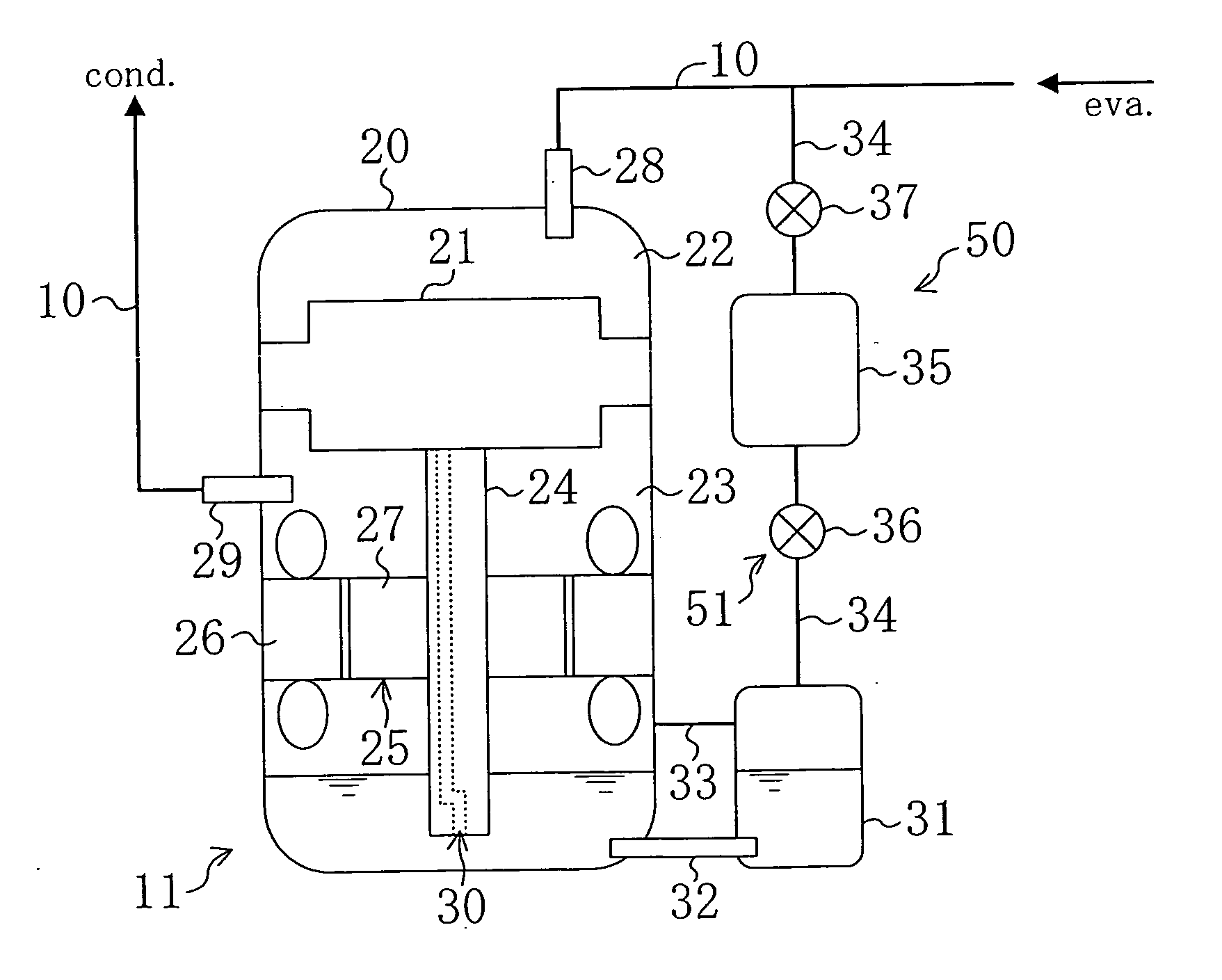
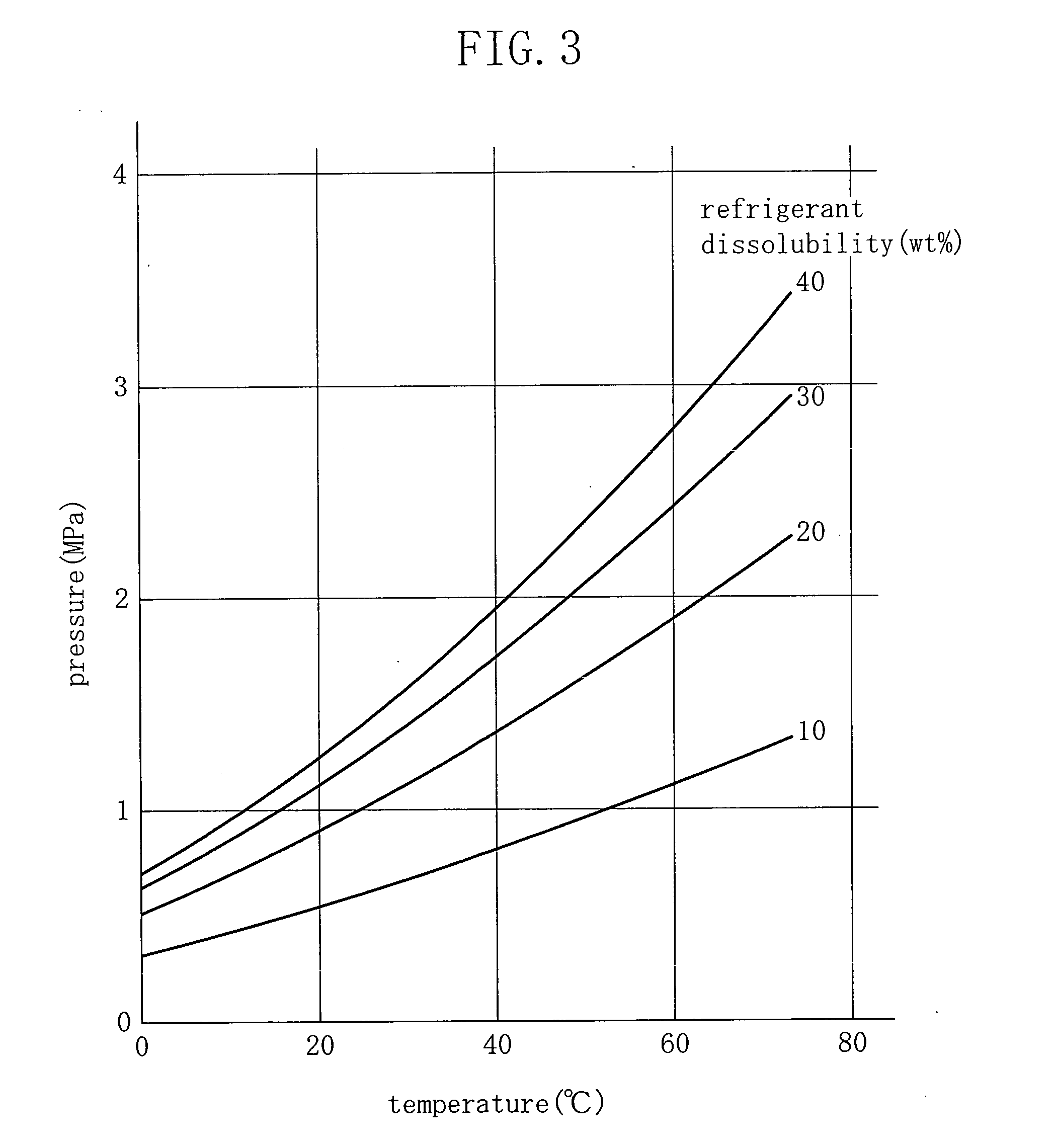
[0032] According to the hermetic compressor (11) of the present invention, the pressure reduction means (50) sucks the gas refrigerant in the container member (31) to reduce the inside pressure of the container member (31). When the inside pressure of the container member (31) is reduced, the pressure of the lubricant oil is immediately reduced and the dissolubility of the refrigerant to the lubricant oil is also lowered. In turn, the refrigerant dissolving in the lubricant oil is gasified, with a result that the viscosity of the lubricant oil is instantly recovered. Hence, the refrigerant dissolving in the lubricant oil is gasified and the viscosity thereof is recovered in shorter period in the present invention than that in the conventional case where the refrigerant dissolving in the lubricant oil is gasified by heating the lubricant oil by a heater wound around the casing (20). As a result, lubrication malfunction caused due to lowering of the viscosity of the lubricant oil by dissolution of the refrigerant thereto can be surely avoided and the reliability of the hermetic compressor (11) can be enhanced.
[0033] Further, according to the hermetic compressor (11) in the third embodiment, the switching mechanism (51) operates to communicate the gas container (35), of which inside pressure is reduced, with the container member (31), so that the inside pressure of the container member (31) is reduced. In other words, the container member (31) does not directly communicate with the intake pipe (28) though the inside pressure of the container member (31) is reduced by utilizing the intake pipe (28) of reduced pressure in the hermetic compressor (11). For this reason, the inside pressure of the container member (31) is not so reduced as that of the intake pipe (28) even under reduced pressure, which prevents excessive flow of the lubricant oil to the container member (31). Thus, according to the present invention, the level of the lubricant oil in the high pressure chamber (23) is prevented from being excessively lowered at the pressure reduction in the container member (31), whereby the oil supply pump (30) can surely continue to supply the lubricant oil in the high pressure chamber (23) to the compression mechanism (21).
[0034] Further, according to the sixth invention, the container member (31) is arranged so as to communicate with the hermetic compressor (11) at a part lower than the level at which the oil supply pump (30) sucks the lubricant oil. Also, in the state of two-layer separation of the liquid refrigerant and the lubricant oil, the liquid refrigerant in the high pressure chamber (23) flowing in the container member (31) is evaporated. Thus, the boundary between the liquid refrigerant and the lubricant oil in the tow-layer separation does not reach the level above the part where the high pressure chamber (23) communicates with the container member (31), so that the oil supply pump (30) always supplies the lubricant oil. Thus, according to the present invention, the oil supply pump (30) is prevented from supplying the liquid refrigerant in the two-layer separation to the compression mechanism (21), with a result that the lubrication malfunction in the compression mechanism (21) can be surely prevented and the reliability of the hermetic compressor (11) can be enhanced.
[0035] In addition, according to the seventh invention, the conduction of the electric heater (53) heats the lubricant oil in the container member (31), independent from the operation of the hermetic compressor (11), to gasify the refrigerant dissolving in the lubricant oil, which recovers the viscosity of the lubricant oil. Moreover, the electric heater (53) heats the liquid refrigerant in the container member (31) to evaporate it even in the two-layer separation of the liquid refrigerant and the lubricant oil. Hence, according to the present invention, the conduction of the electric heater (53) before activation enables to recover the viscosity of the lubricant oil, which surely prevents the lubrication malfunction in the compression mechanism (21) immediately after the activation and further enhances the reliability of the sealed compression mechanism (11).

Problems solved by technology

For this reason, a considerable amount of refrigerant dissolves in the lubricant oil in a state when the external temperature is low or the like, which may lower the viscosity of the lubricant oil.
When the compressor is driven under the condition that the viscosity thereof remains low, the lubricant oil of such low viscosity is supplied to the compression mechanism, which may cause lubrication malfunction and damage to the compressor.

Method used


Image

  • Hermetic compressor
  • Hermetic compressor
  • Hermetic compressor

Examples


first embodiment

[0047] The present embodiment refers to a refrigerator (1) provided with a hermetic compressor (11) according to the present invention.

[0048]

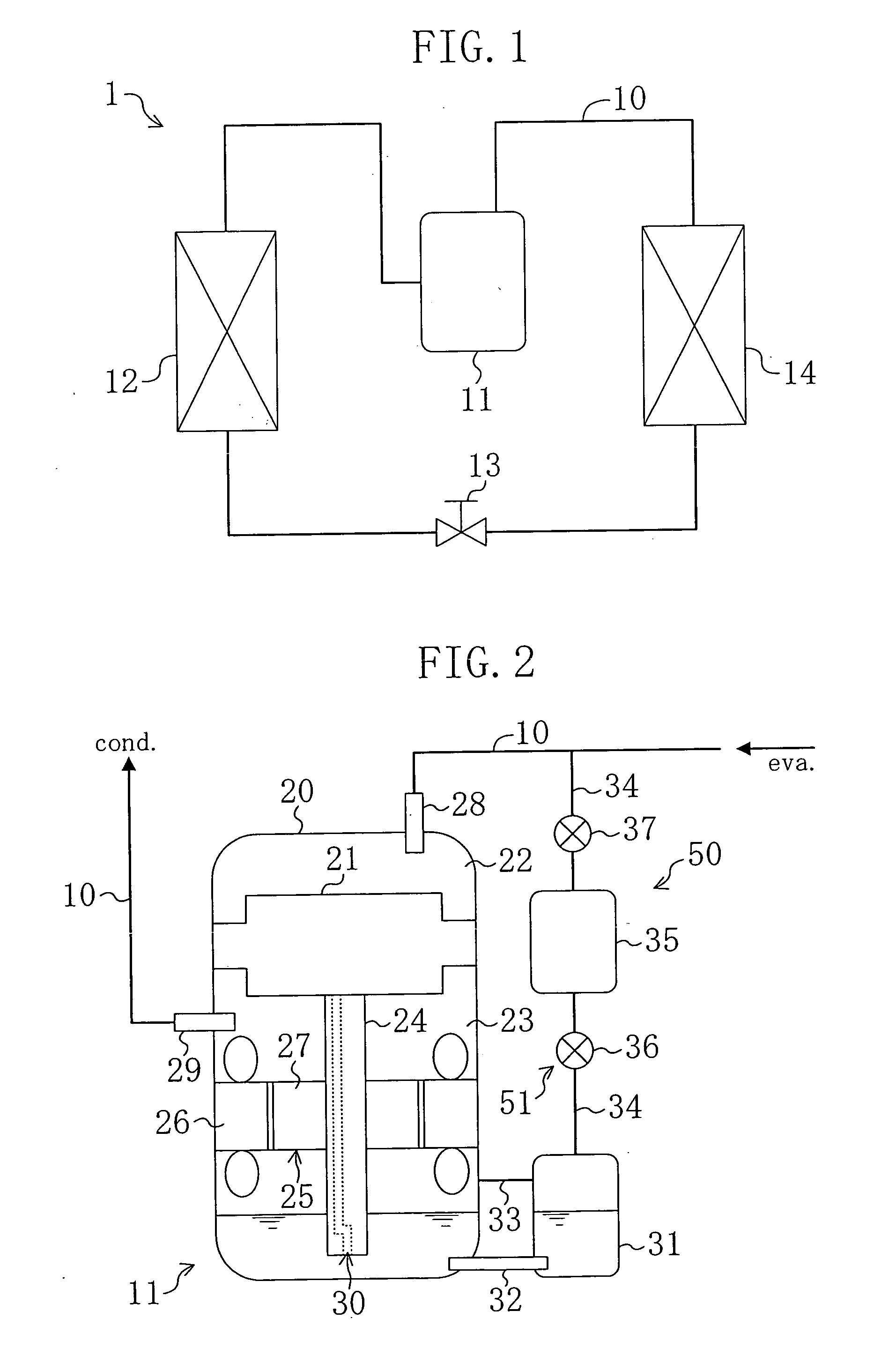
[0049] As shown in FIG. 1, the refrigerator (1) is provided with a refrigerant circuit (10) that is a closed circuit so composed that the hermetic compressor (11), a condenser (12), an expansion valve (13) and an evaporator (14) are sequentially connected through pipes. In the refrigerant circuit (10), R410A, R407C or the like, which are HFC refrigerants, is filled as a refrigerant.

[0050]

[0051] As shown in FIG. 2, the hermetic compressor (11) has a closed structure as a whole, and includes a longitudinal, cylindrical casing (20).

[0052] A compression mechanism (21) and an electric motor (25) are provided within the casing (20). The compression mechanism (21) is connected to the electric motor (25) by means of a vertically extending drive shaft (24).

[0053] The compression mechanism (21) is of scroll type fluid mechanism and includes a fixed s...

second embodiment

[0092] The second embodiment of the present invention is a modification of the pressure reduction means (50) in the hermetic compressor (11) of the first embodiment. Herein, the features different from those in the first embodiment will be described as the present embodiment.

[0093] As shown in FIG. 6, a three-way valve (38) is provided as the switching mechanism in the communication pipe (34) in the present embodiment. The gas container (35) in the present embodiment is connected to the communication pipe (34) via the three-way valve (38). Further, the communication pipe (34), the gas container (35) and the three-way valve (38) compose the pressure reduction means (50) in the present embodiment.

[0094] The three-way valve (38) is connected at a first port thereof to the gas container (35), at a second port thereof to the communication pipe (34) on the liquid retainer (31) side and at a third port thereof to the communication pipe (34) on the intake pipe (28) side. The three-way val...

third embodiment

of the Invention

[0100] The third embodiment of the present invention is a modification of the pressure reduction means (50) in the hermetic compressor (11) of the first embodiment. Herein, the features different from those in the first embodiment will be described as the present embodiment.

[0101] As shown in FIG. 7, a capillary tube (39) and a solenoid valve (52) are provided in the communication pipe (34) in the present embodiment. The solenoid valve (52) is arranged on the intake (28) side of the capillary tube (39) in the communication pipe (34). When the solenoid valve (52) is opened, the liquid retainer (31) and the intake pipe (28) communicate with each other through the capillary tube (39). The communication pipe (34), the capillary tube (39) and the solenoid valve (52) compose the pressure reduction means (50) in the present embodiment.

[0102] When the viscosity of the lubricant oil obtained from the detected values of the temperature sensor and the pressure sensor is highe...


PUM


Abstract

A high pressure chamber in a casing communicates at the bottom thereof with a liquid retainer. A communication pipe is connected at one end thereof to the upper end of the liquid retainer and connected at the other end thereof to an intake pipe. A gas container and first and second solenoid valves are provided in the communication pipe. When the first solenoid valve is closed and the second solenoid valve (37) is opened, the gas container communicates with the intake pipe to reduce the pressure in the gas container. Thereafter, when the first solenoid valve is opened and the second solenoid valve (37) is closed, the gas container communicates with the liquid retainer to reduce the pressure in the liquid retainer. Then, the pressure of lubricant oil in the liquid retainer is lowered to gasify a refrigerant dissolving in the lubricant oil. As a result, lubrication malfunction caused due to lowering of the viscosity of the lubricant oil by dissolution of the refrigerant therein is avoided and the reliability of the hermetic compressor is enhanced.

Description

FIELD OF THE INVENTION [0001] The present invention relates to a hermetic compressor and a countermeasure for preventing lubrication malfunction therein. BACKGROUND ART [0002] Conventionally, hermetic compressors have been widely known. For example, such hermetic compressors are provided in refrigerant circuits for refrigerators or air conditioners and are widely used for compressing refrigerants. In general, the hermetic compressors each include a casing as a sealed container and a compression mechanism accommodated within the casing. In the hermetic compressors, lubricant oil retained at the bottom of the casing is supplied to the compression mechanism and the like for lubrication. [0003] In a hermetic compressor of this type, lubricant oil and a gas refrigerant coexist within the casing. For this reason, a considerable amount of refrigerant dissolves in the lubricant oil in a state when the external temperature is low or the like, which may lower the viscosity of the lubricant oi...

Claims


Application Information

Patent Timeline
Patent Type & Authority Applications(United States)
IPC IPC(8): F04B15/08F04B39/00F04B39/02F04C18/02F04C23/00F04C29/02F04C29/12
CPCF04B15/08F04B39/02F04B39/0207F04B39/0284F04C2270/48F04C29/02F04C29/026F04C2210/14F04C2210/24F04C23/008Y10S417/902F04C29/00F25B1/00
Inventor HIROOKA, KATSUMIHIKAWA, TAKESHI
Owner DAIKIN IND LTD
Learn More