Multiple-serial-hydrofoil swim fins statement regarding federally sponsored R&D

a technology of swim fins and hydrofoil, applied in the field of swim fins, can solve the problems of difficulty in following the logic of the claim of “fish” based propulsion, increase the work necessary to move the swim fin, and extra length increase the overall length of the swim fin, so as to reduce the outward directed vortice, high propulsion and low drag.

Inactive Publication Date: 2005-08-11
MELIUS JOHN DAVID
View PDF8 Cites 2 Cited by
  • Summary
  • Abstract
  • Description
  • Claims
  • Application Information

AI Technical Summary

Benefits of technology

[0032] It is yet another object of the present invention to provide swim fin designs which can be kicked across the water's surface without catching or stopping abruptly on the water's surface as they re-enter the water after having been raised above the surface.
[0033] It is yet another object of the present invention to provide swim fin designs which provide high levels of propulsion and low levels of drag when used at the surface as well as below the surface.
[0034] It is yet another object of the present invention to provide swim fin designs which provide high levels of propulsion and low levels of drag even when significantly short and gentle kicking strokes are used.
[0035] It is yet another object of the present invention to provide hydrofoil designs which significantly reduce outward directed vortices along their attacking surface.
[0036] It is yet another object of the present invention to provide hydrofoil designs which efficiently encourage the fluid medium along their attacking surface to flow away from their outer side edges and toward their center axis so that fluid pressure is increased along their attacking surface.
[0037] It is yet another object of the present invention to provide swim fin designs which significantly reduce the occurrence of ankle and leg fatigue.

Problems solved by technology

Without using a structure related to the shape of a fish, it is difficult to follow the logic of the claim of “fish” based propulsion.
Some sort of lengthy stiff portion is common in most swim fins and this extra length increases the amount of work necessary to move the swim fin through the water because of the physics involved in moving weight at a distance involving centrifugal force due to the length of the stiff section.
The extra length increases the overall length of the swim fin (usually adding to the cost of manufacturing the swim fin and the difficulty of storage and traveling with a longer swim fin).
The airfoils in these patents are parallel in alignment, and hinged without providing self-regulating pitch to the flow of water over the foils making them ineffective by allowing the airfoils to pivot instead of causing useful lift.
More importantly, this patent does not teach a method or apparatus for creating a flow of water over the airfoil shape at a proper angle of attack (self-regulating pitch).
Without facilitating a flow of water at the proper pitch, there is no useful “lift” produced to aid in propulsion.
This patent does not teach the use of a flexible blade or any hydrodynamic airfoil shapes used to create “lift” to aid in propulsion.

Method used


Image

  • Multiple-serial-hydrofoil swim fins statement regarding federally sponsored R&D
  • Multiple-serial-hydrofoil swim fins statement regarding federally sponsored R&D
  • Multiple-serial-hydrofoil swim fins statement regarding federally sponsored R&D

Examples


Embodiment Construction

)

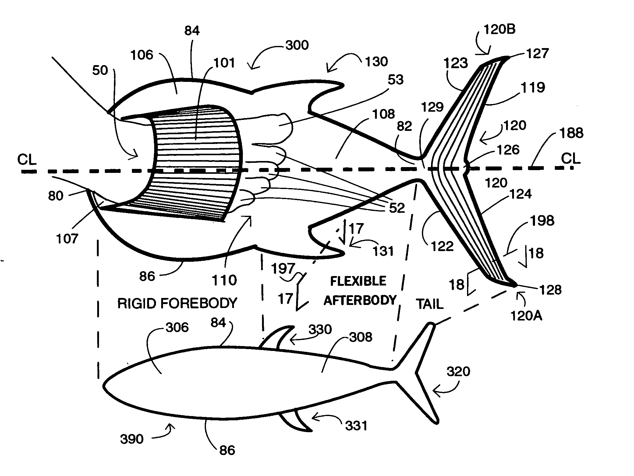
[0155] Selected shapes enhance the effectiveness of foot fins because certain shapes, most notably airfoil shapes, and cause the fluid (water) to flow more quickly over one surface than it flows over the opposite surface producing a negative pressure hereafter referred to as “lift”. (Ref. Bernoulli effect). This negative pressure causes the swim fin to move in that direction. Airplane wings (airfoil shapes) offer an example of a most efficient way of moving through water and light fluids such as air using “lift”. The great advantage of using lift occurs when the lifting forces passively work by simply holding an airfoil in a moving stream of water at the proper angle of attack (pitch) with the negative pressures creating propulsive force vectors.

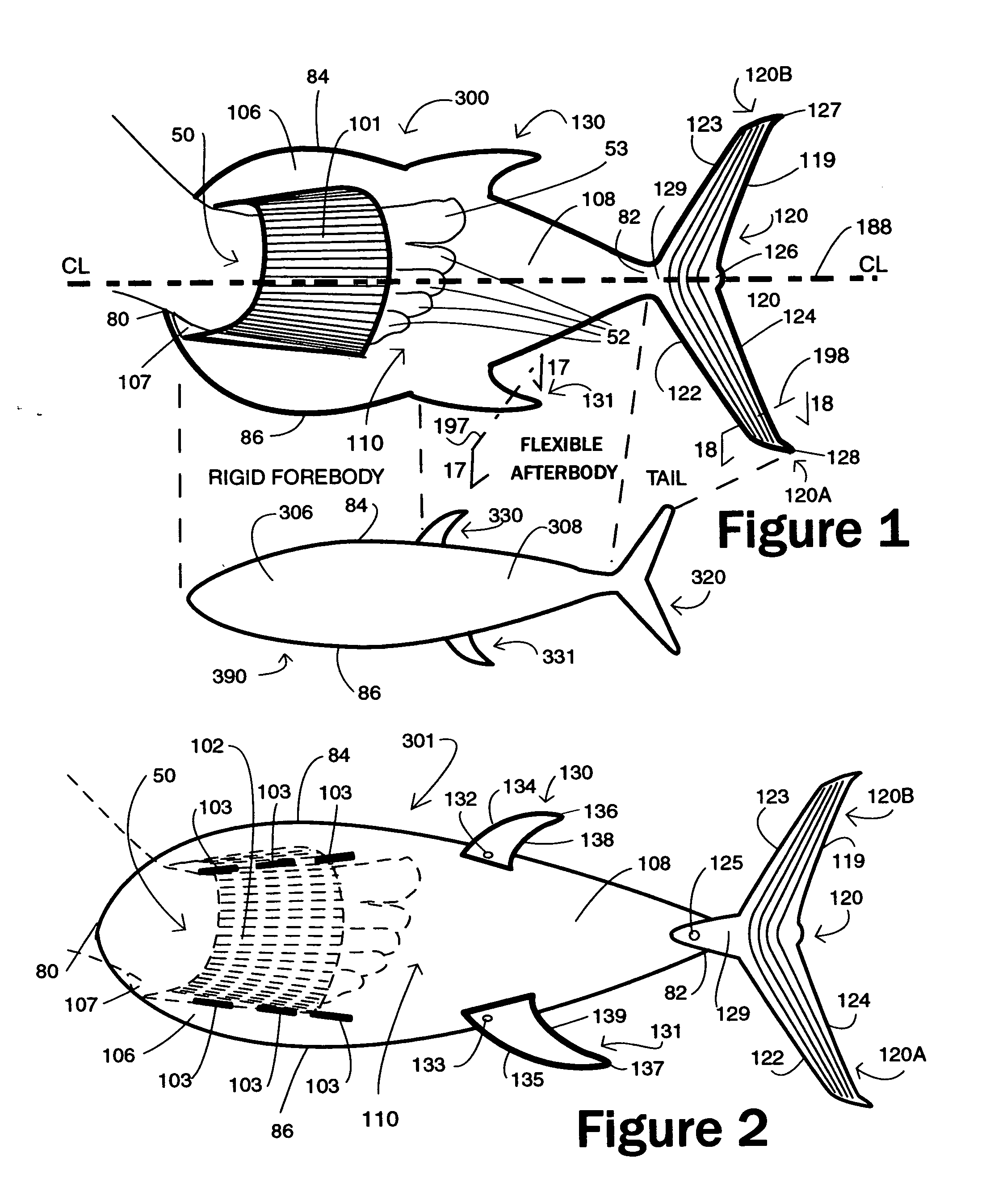
[0156]FIG. 18 is a cross-section view of the hydrofoil portion of the tail fin 120 which the dashed line 198 in FIG. 1 acts as the section line and describes some of the known aspects of this airfoil. The cross-section of the tail fin 120 ...


PUM


Abstract

MULTIPLE-SERIAL-HYDROFOIL swim fins use aerodynamic shapes to help with propulsion through the water. By producing “lift” as an additional power source for swimming, they provide more power for the swimmer without additional effort from the swimmer. The planar blade helps to provide self-regulating pitch for the hydrodynamic shapes. The overall reduction in the size and cost of the swim fin is a secondary benefit to the reduction in work for the swimmer. By having multiple self-regulating airfoils (hydrofoils when used in water) in a series properly distanced from one another, the accelerated flow of water over the hydrodynamic shapes increases the effectiveness of the trailing hydrodynamic shapes through serial amplification. The geometry of the swim fins work with high performance materials using sophisticated internal properties (compliant geometry) to manage the self-regulating pitch and serial amplification.

Description

RELATED APPLICATIONS [0001] This patent application is a continuation of U.S. provisional patent application Ser. No. 60 / 42020 filed Nov. 6, 2002 for MULTIPLE HYDORFOILS FISH STYLE SWIM FIN, which application is incorporated herein by this reference thereto.STATEMENT REGARDING FEDERALLY SPONSORED R&D [0002] Not applicable INCORPORATION-BY-REFERENCE OF MATERIAL SUBMITTED ON A COMPACT DISC [0003] Not applicable BACKGROUND [0004] 1. Field of Invention [0005] This invention relates to swim fins and more particularly swim fins of an advanced design for swimming and diving at water level and below the water, and more particularly to swim fins employing aerodynamic shapes (hydrodynamic shapes when used in water) attached to the sides of a planar blade and employing an aerodynamic shaped tail fin. By having multiple hydrodynamic shapes in a series with a set distance from one another, the accelerated flow of water produced from the forward hydrodynamic shapes increases the effectiveness of ...

Claims


Application Information

Patent Timeline
Patent Type & Authority Applications(United States)
IPC IPC(8): A63B31/08A63B31/11
CPCA63B31/11
Inventor MELIUS, JOHN DAVID
Owner MELIUS JOHN DAVID
Why Eureka
Try Eureka