Batch testing system and method for wireless communication devices

a wireless communication device and wireless communication technology, applied in the field of batch testing system and method for wireless communication devices, can solve the problems of inefficiency of conventional testing methods, idle other devices, and high time consumption of devices under test, and achieve the effect of reducing the strength of reflected signals

Inactive Publication Date: 2005-08-11
ACCTON TECHNOLOGY CORPORATION
View PDF7 Cites 80 Cited by
  • Summary
  • Abstract
  • Description
  • Claims
  • Application Information

AI Technical Summary

Benefits of technology

[0007] The present invention employs a single shielded anechoic chamber to perform batch testing of wireless communication devices. Besides external electromagnetic interference (EMI), the shielded anechoic chamber can also avoid superfluous reflection paths during testing. This is contributed to inner walls of the chamber with particular material, which can absorb most energy of the incident signal upon the inner walls and reduce strength of the reflected signal significantly. Thus, the shielded anechoic chamber can avoid signal instability resulted from the multi-path effect. The present invention also provides a design of the batch container and installation mechanism within the shielded anechoic chamber, thereby facilitating the batch testing of wireless communication devices to upgrade testing performance.

Problems solved by technology

However, the conventional testing method only installs and tests a product in the chamber at a time.
When a lot of products are tested, much time would be spent in the installation of devices under test (DUTs), and other devices are idle other than the DUT.
Therefore, the conventional testing method lacks efficiency.
But, this would increase testing cost, such as the cost of instruments and labor powers.
Hence, for the manufacturers who need to test a large number of wireless products rapidly and inexpensively, the conventional method for batch testing is very short of efficiency.
Therefore, this conventional method for batch testing cannot provide a full and reliable testing report for wireless products.

Method used


Image

  • Batch testing system and method for wireless communication devices
  • Batch testing system and method for wireless communication devices
  • Batch testing system and method for wireless communication devices

Examples


Embodiment Construction

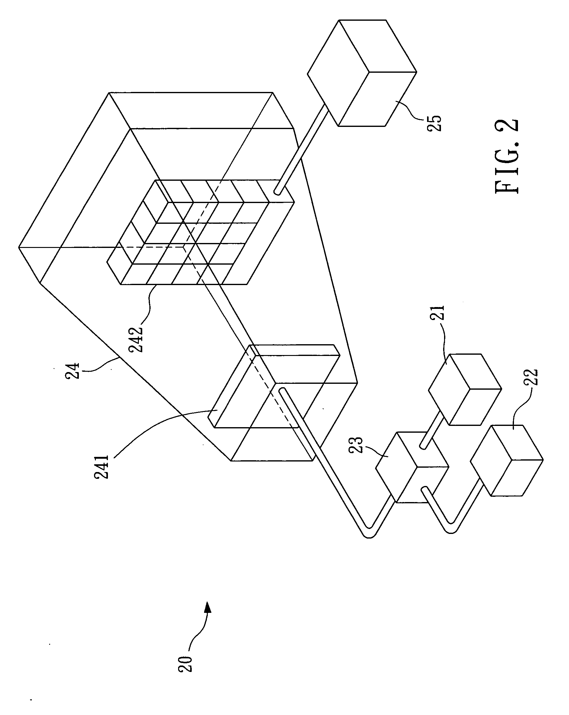
[0018] This section will explain the present invention in detail with preferred embodiments and appended drawings. FIG. 2 is a schematic view showing a preferred embodiment of the batch testing system according to the present invention. In FIG. 2, the batch testing system 20 is used to test a plurality of wireless communication devices, such as wireless network interface cards, wireless access points, wireless communicators, etc. The batch testing system 20 includes a signal generator 21 for generating a first testing signal. To obtain better testing performance, a Golden Sample of the wireless communication device under test (DUT) can be used as the signal generator 21. The Golden Sample conforms to associated standards and specifications much closer than the DUT, thus its signal quality is better for testing. Besides, a vector signal generator, or combined with a power amplifier, can also be used as the signal generator 21 to generate signals.

[0019] The batch testing system 20 al...


PUM


Abstract

The present invention provides a batch testing system and method that applies a single shielded anechoic chamber to simultaneously test multiple wireless communication devices. The shielded anechoic chamber can avoid external electromagnetic interference, reduce strength of reflected signals significantly and provide stable channel environment, thereby testing signal transceiving of the wireless communication devices more precisely. The present invention also provides a design for the batch container and loading mechanism within the chamber.

Description

BACKGROUND OF THE INVENTION [0001] (a). Field of the Invention [0002] The present invention relates in general to a batch testing system and method for wireless communication devices, and more particularly to a system and method that tests multiple wireless communication devices simultaneously within a shielded anechoic chamber. [0003] (b). Description of the Prior Arts [0004] In recent years, cellular phones and wireless local area networks (WLAN) are in widespread use with the rapid development of wireless communication technologies. For manufacturers of wireless products such as cellular phones, wireless network interface cards, wireless access points, etc., signal transceiving of the products is mostly tested in shielded anechoic chambers. However, the conventional testing method only installs and tests a product in the chamber at a time. When a lot of products are tested, much time would be spent in the installation of devices under test (DUTs), and other devices are idle other...

Claims


Application Information

Patent Timeline
Patent Type & Authority Applications(United States)
IPC IPC(8): G01R29/08H04B17/00H04M1/00
CPCH04B17/0085G01R29/0821
Inventor LIU, I-RU
Owner ACCTON TECHNOLOGY CORPORATION
Why Eureka
Try Eureka