Portable telephone

Inactive Publication Date: 2005-08-11
KYOCERA CORP
View PDF11 Cites 33 Cited by
  • Summary
  • Abstract
  • Description
  • Claims
  • Application Information

AI Technical Summary

Benefits of technology

[0005] An object of the present invention is to provide a portable te

Problems solved by technology

However, these conventional portable telephone apparatuses exploit current location information simply to perform a previously determined operation, and such a capability is not very

Method used


Image

  • Portable telephone
  • Portable telephone
  • Portable telephone

Examples


Embodiment Construction

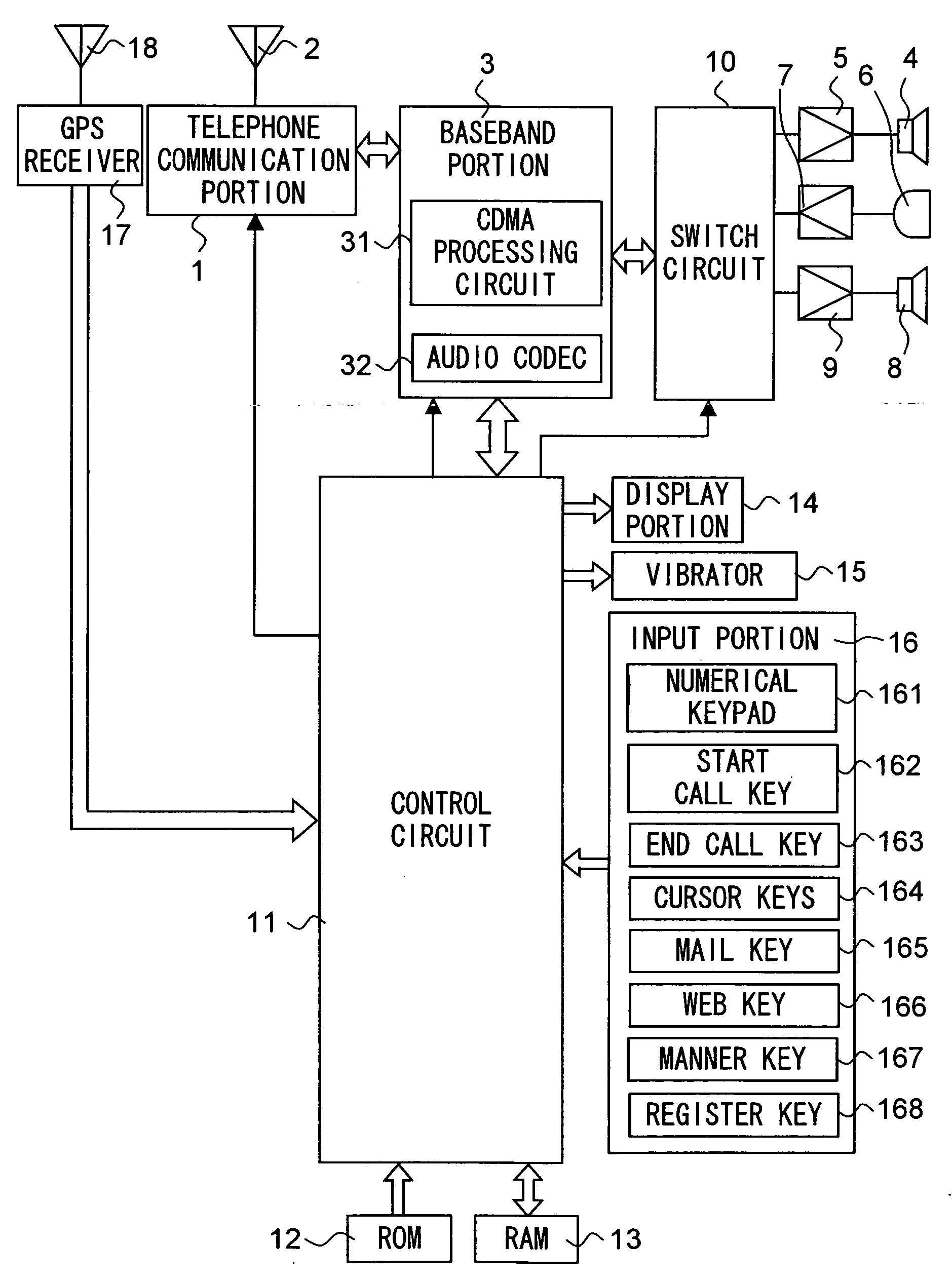
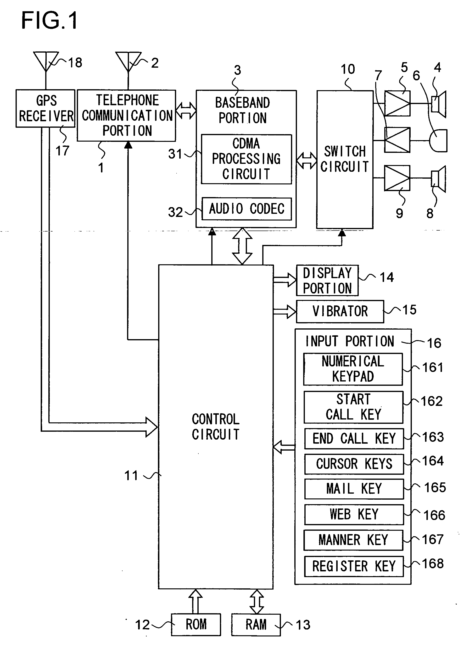
[0015] Hereinafter, an embodiment of the present invention will be described with reference to the drawings. FIG. 1 is a block diagram showing the configuration of a principal portion of a portable telephone apparatus according to the invention. Reference numeral 1 represents a telephone communication portion that transmits a signal from a baseband portion 3, which will be described later, to a base station via an antenna 2 and that receives a radio wave from the base station via the antenna 2.

[0016] Reference numeral 3 represents a baseband portion having a CDMA processing circuit 31 and an audio codec 32. The CDMA processing circuit 31 performs code division multiple access, scrambling, error control, and timing detection. The audio codec 32 performs compression (encoding), decompression (decoding), and analog / digital conversion of sound, and also adjusts the volume of reproduced sound and the sensitivity of a microphone by controlling internally provided amplifier circuits (not ...


PUM


Abstract

A portable telephone comprising a GPS receiving section (17) for detecting the current position, an input section (16) having one or more key, a RAM 13 for storing a registered operating order of the keys and registered positional conditions, and a control circuit (11) for executing the operating procedure of the keys stored in the RAM (13) when a current position detected at the GPS receiving section (17) satisfies the positional conditions stored in the RAM (13), wherein the positional conditions specifies one point or the position of an area, and adds a distance exceeding the positional detection accuracy to a specified position.

Description

TECHNICAL FIELD [0001] The present invention relates to a portable telephone apparatus that can detect current location information. BACKGROUND ART [0002] Some conventionally known portable telephone apparatuses are capable of calculating the current location of themselves by receiving the location of a plurality of base stations, or capable of calculating the current location from the data received by a GPS (global positioning system) receiver. Correspondingly, there have been developed various ways of exploiting such current location information, as by making a portable telephone apparatus perform a predetermined operation according to its current location. [0003] For example, Japanese Patent Application Laid-Open No. 2000-285382 discloses a portable telephone apparatus that automatically sends an electronic mail message when it reaches a predetermined location. On the other hand, Japanese Patent Application Laid-Open No. 2001-160985 discloses a system in which the current locatio...

Claims


Application Information

Patent Timeline
IPC IPC(8): H04M1/00H04M1/72457H04M1/72451H04W4/02H04W64/00
CPCH04M1/72566H04M2250/10H04M1/72572H04M1/72451H04M1/72457H04B1/40H04M1/725H04M3/42
Inventor TANAKA, SHIGEYUKI
Owner KYOCERA CORP
Why Eureka
Try Eureka