
System and method of selection and communication of a disk for storage of a coredump

a disk and coredump technology, applied in the field of file servers, can solve the problem that the disk is not otherwise accessible, and achieve the effect of reducing rapid taking over and restoring, and minimizing the impact of disk spa

Active Publication Date: 2005-08-11
NETWORK APPLIANCE INC
View PDF13 Cites 18 Cited by
  • Summary
  • Abstract
  • Description
  • Claims
  • Application Information

AI Technical Summary

Benefits of technology

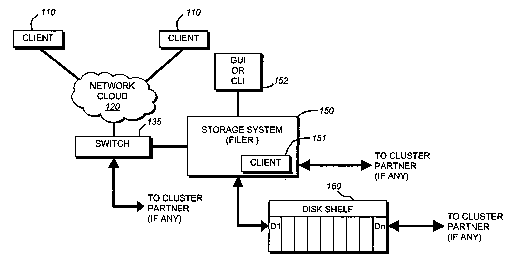
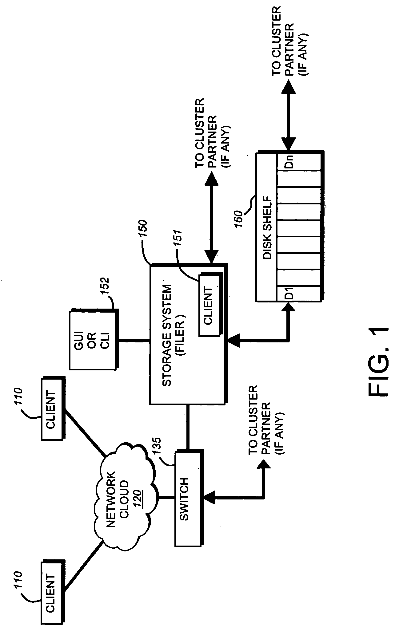
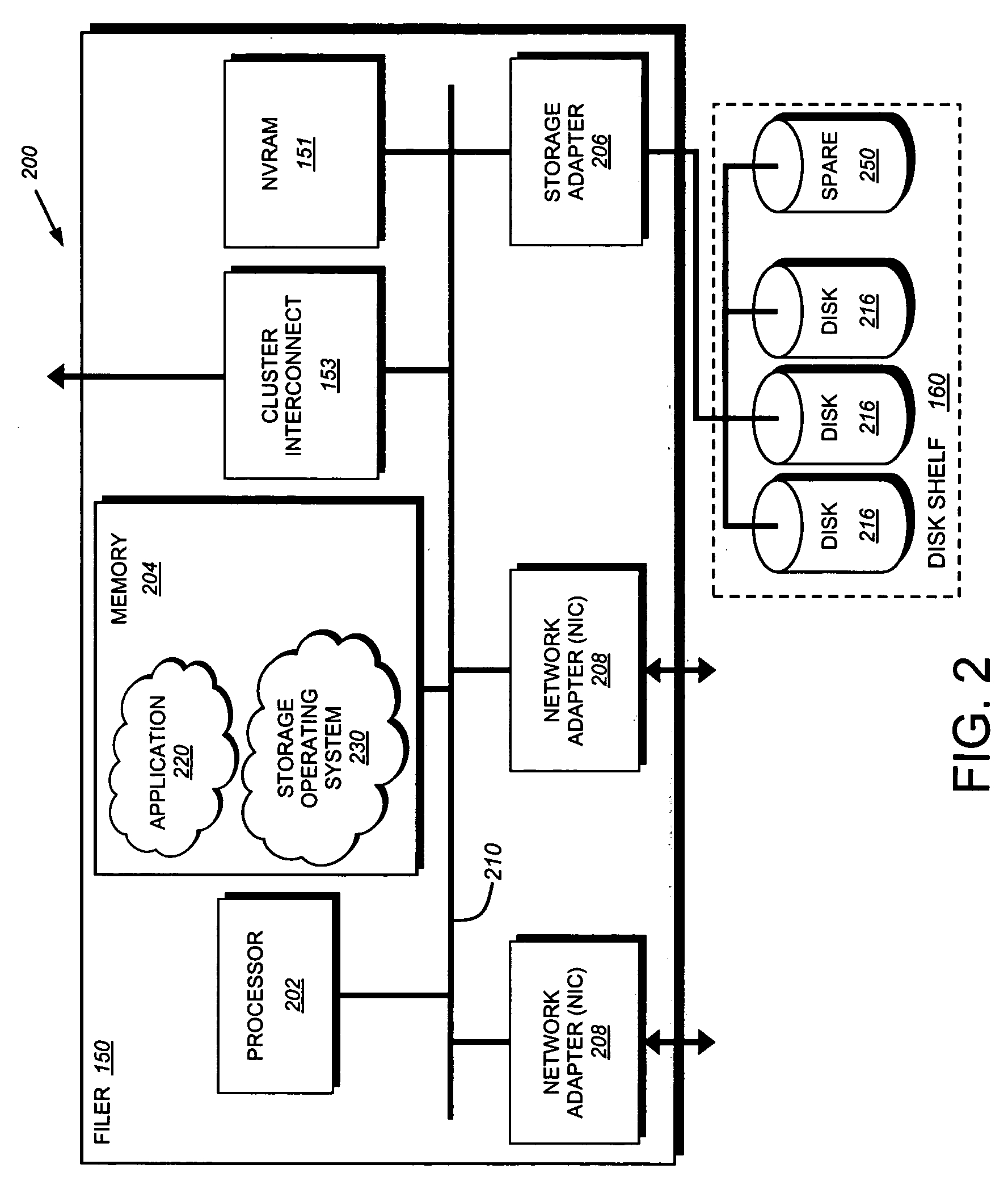
[0020] This invention overcomes the disadvantages of the prior art by providing a system and method for selecting and communicating a single disk (a “coredump disk”) for use in a coredump procedure by a failed file server (or filer). In particular, the failed filer writes the coredump data to a single “coredump disk.” This enables useful modes of coredump in both standalone and cluster filer environments. In all environments, it enables handling of coredump from very large memory systems with only a few disks, minimization of wasted disk space due to coredump, and minimization of the impact on normal / regular file service. For example, in both standalone and cluster environments, the use of a single coredump disk that is not involved in regular file services prevents interference of I / O (input / output) required for the coredump recovery “savecore” process with normal file services I / O. In a cluster environment, this enables a cluster filer to rapidly take over and restore regular file services on behalf of its partner, because the takeover can proceed in parallel with an independently of the coredump. In a SAN environment with a cluster of tightly or loosely coupled filers, it enables sharing of a single disk between multiple filers for coredump.

Problems solved by technology

Because the coredump spreads the coredump over multiple disks, those disks are not otherwise accessible to the partner filer to begin the takeover process.

Method used


Image

  • System and method of selection and communication of a disk for storage of a coredump
  • System and method of selection and communication of a disk for storage of a coredump
  • System and method of selection and communication of a disk for storage of a coredump

Examples


Embodiment Construction

[0035] The teaching of this invention can be adapted to a variety of storage system architectures, but not limited to, a network-attached storage environment, a storage attached network, and a disk assembly directly attached to a client / host computer. The term “storage system” should therefore be taken broadly to include such arrangements. However, it should be understood that the teachings of this invention can be applied to any server systems. It is expressly contemplated that the various processes, architectures and procedures described herein can be implemented in hardware, firmware or software, consisting of a computer-readable medium including program instructions that perform a series of steps.

[0036] Should the reader already be familiar with the general discussion of a file server environment and the process of conducting coredump with a single disk, then he or she is invited to refer directly to the last section of this Description entitled Selection of Coredump Disk.

Fil...


PUM


Abstract

This invention provides a system and method for selecting and communicating a single disk (a “coredump disk”) for use in a coredump procedure by a failed file server (or filer). A selection method on the failed filer determines the “best candidate” coredump disk according to a predetermined set of criteria. For example, the available disks that can receive coredump data are located and ordered so as to prefer disks that best match the coredump data size requirement, are least likely to be needed for normal service by the server; and require the least preparation to receive coredump data. Appropriate attributes on the selected coredump disk are written to indicate that a coredump is in progress, and the location of the coredump data. Upon reboot of the failed filer (or takeover by a cluster partner), the coredump disk is identified and the coredump data recovered by reading back appropriate attributes.

Description

RELATED APPLICATION [0001] The invention is related to U.S. patent application Ser. No. ______ [Attorney Docket No. 112056-0131] entitled SYSTEM AND METHOD FOR TAKEOVER OF PARTNER RESOURCES IN CONJUNCTION WITH COREDUMP, filed on even date herewith, and is incorporated herein by reference.FIELD OF THE INVENTION [0002] The present invention relates to file servers and more particularly to the bulk transfer or “dump” of file server memory contents for diagnostic purposes during a panic or failure. BACKGROUND OF THE INVENTION File Servers [0003] A file server (also termed herein “filer”) is a computer that provides file services relating to the organization of information on storage devices, such as disks. A file server or filer includes a storage operating system that implements a file system to logically organize the information as a hierarchical structure of directories and files on the disks. Each “on-disk” file may be implemented as a set of data structures, e.g. disk blocks, conf...

Claims


Application Information

Patent Timeline
Patent Type & Authority Applications(United States)
IPC IPC(8): G06F11/20
CPCG06F11/0709G06F11/0778G06F11/0727
Inventor CASSELL, LOELLYN J.PARKISON, BRIANBOLEN, DAVID BRITTAINCOATNEY, SUSAN M.
Owner NETWORK APPLIANCE INC
Learn More