Vehicle system to recapture kinetic energy

a technology of kinetic energy and drive system, which is applied in the direction of hybrid vehicles, fluid couplings, couplings, etc., can solve the problems of generating electricity, affecting the efficiency of regenerative braking systems, and affecting the rate of charge to the batteries, so as to achieve a small capacity

Active Publication Date: 2005-08-18
PARKER I L L C +1
View PDF18 Cites 47 Cited by
  • Summary
  • Abstract
  • Description
  • Claims
  • Application Information

AI Technical Summary

Benefits of technology

[0028] The fluid drive system may further include a third hydraulic fluid tank that may be a pneumatically charged accumulator tank for storing pressurized hydraulic fluid. The third accumulator tank may receive pressurized hydraulic fluid from the other hydraulic pump / motor during at least a portion of the time the vehicle is decelerating, and pressurized fluid from the third hydraulic fluid tank may power the one hydraulic pump / motor to turn the electric motor and recharge the electrical energy supply source during at least a portion of the time the vehicle is motionless. The hydraulic fluid tank may have a smaller capacity than the second hydraulic fluid tank.

Problems solved by technology

One limitation of typical regenerative braking systems are that they can only generate electricity while the vehicle is still moving, and are not designed to generate any electricity once the vehicle has come to a stop or when the vehicle is accelerating.
Also, it is believed that typical regenerative braking systems are only about 5-10% efficient in returning energy back to the batteries.
Furthermore, the rate of charge to the batteries may spike immediately during regenerative braking and then decline rapidly.
This may be detrimental to the life span of the batteries and associated electronics.
Tsatsis does not show or disclose any means, however, for generating the pressure to drive the turbine by using recycled kinetic energy from the motion of the vehicle.
In a vehicle using electrical energy, the electrical consumption is greatest in volume and rate during initial acceleration, causing most of the energy depletion and loss of range.
Miller does not disclose being able to use the power from hydraulic motor / pump to generate electricity if the accumulator becomes fully pressurized.
In addition, Miller does not disclose how to use a pneumatic system in combination with a hydraulic drive system to provide a dual energy storage system.

Method used


Image

  • Vehicle system to recapture kinetic energy
  • Vehicle system to recapture kinetic energy
  • Vehicle system to recapture kinetic energy

Examples


Embodiment Construction

[0043] For the purposes of promoting an understanding of the principles of the invention, reference will now be made to the embodiments illustrated in the drawings, which will be described below. It will nevertheless be understood that no limitation of the scope of the invention is thereby intended. The invention includes any alterations and further modifications in the illustrated devices and described methods and further applications of the principles of the invention which would normally occur to one skilled in the art to which the invention relates.

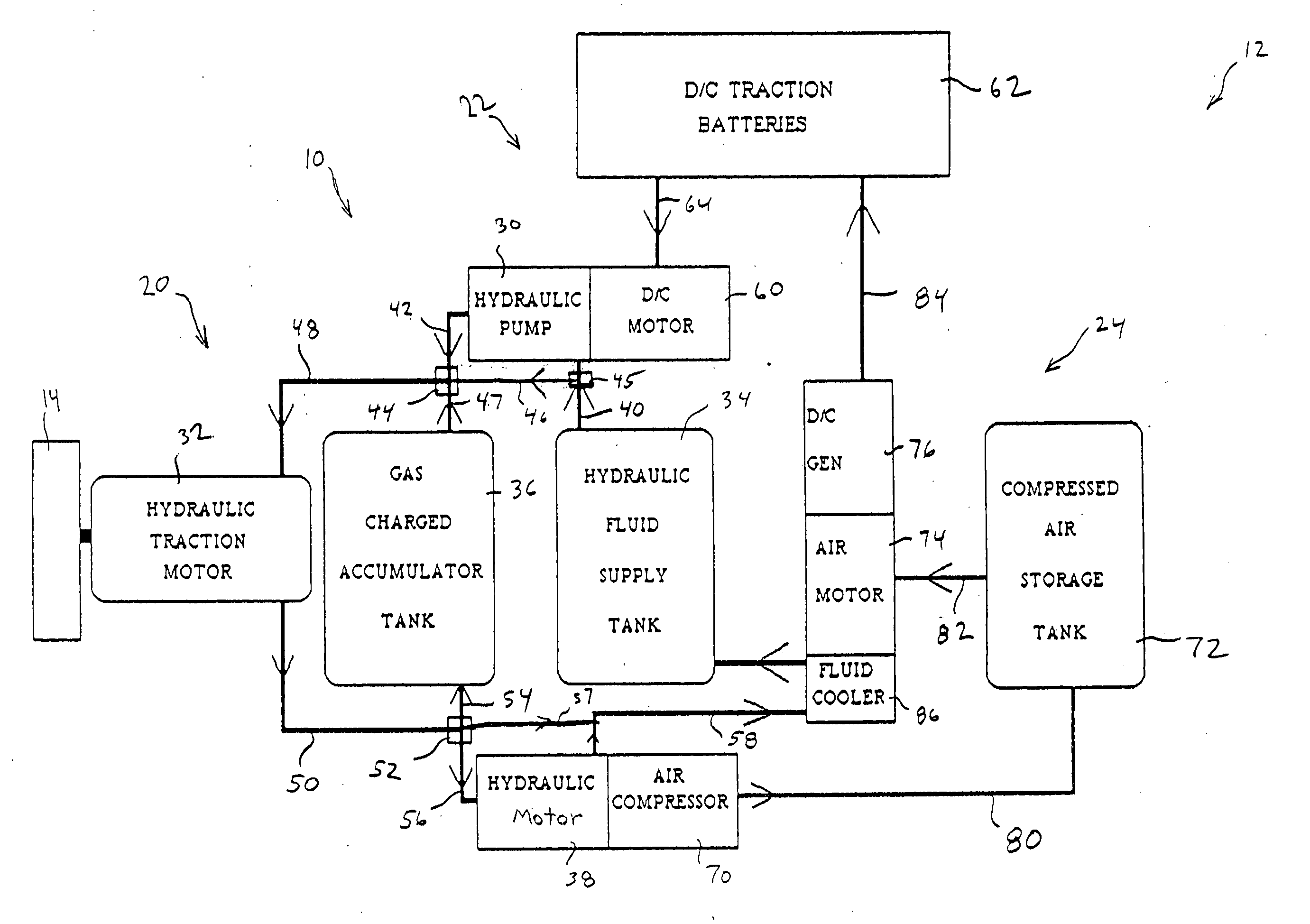
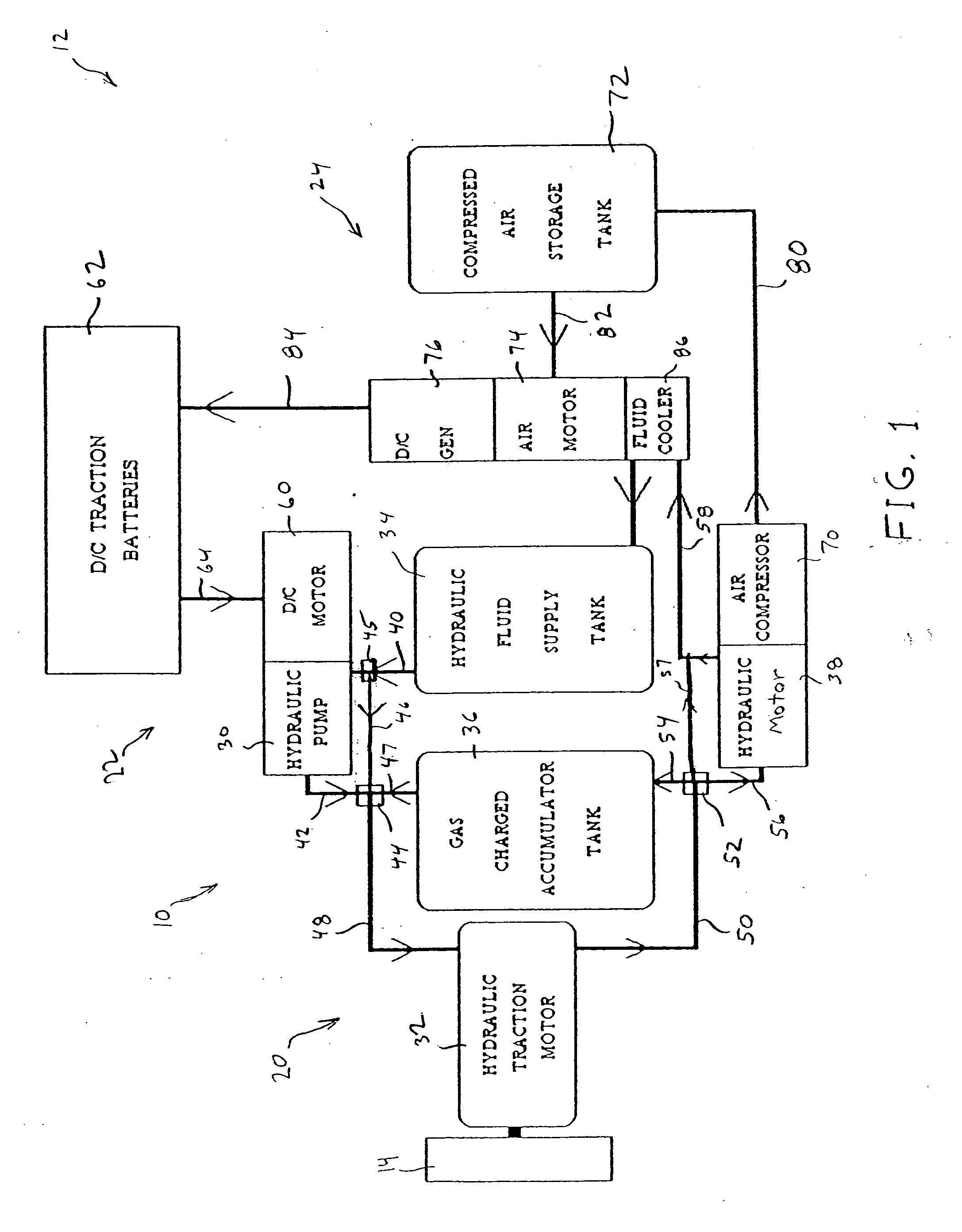
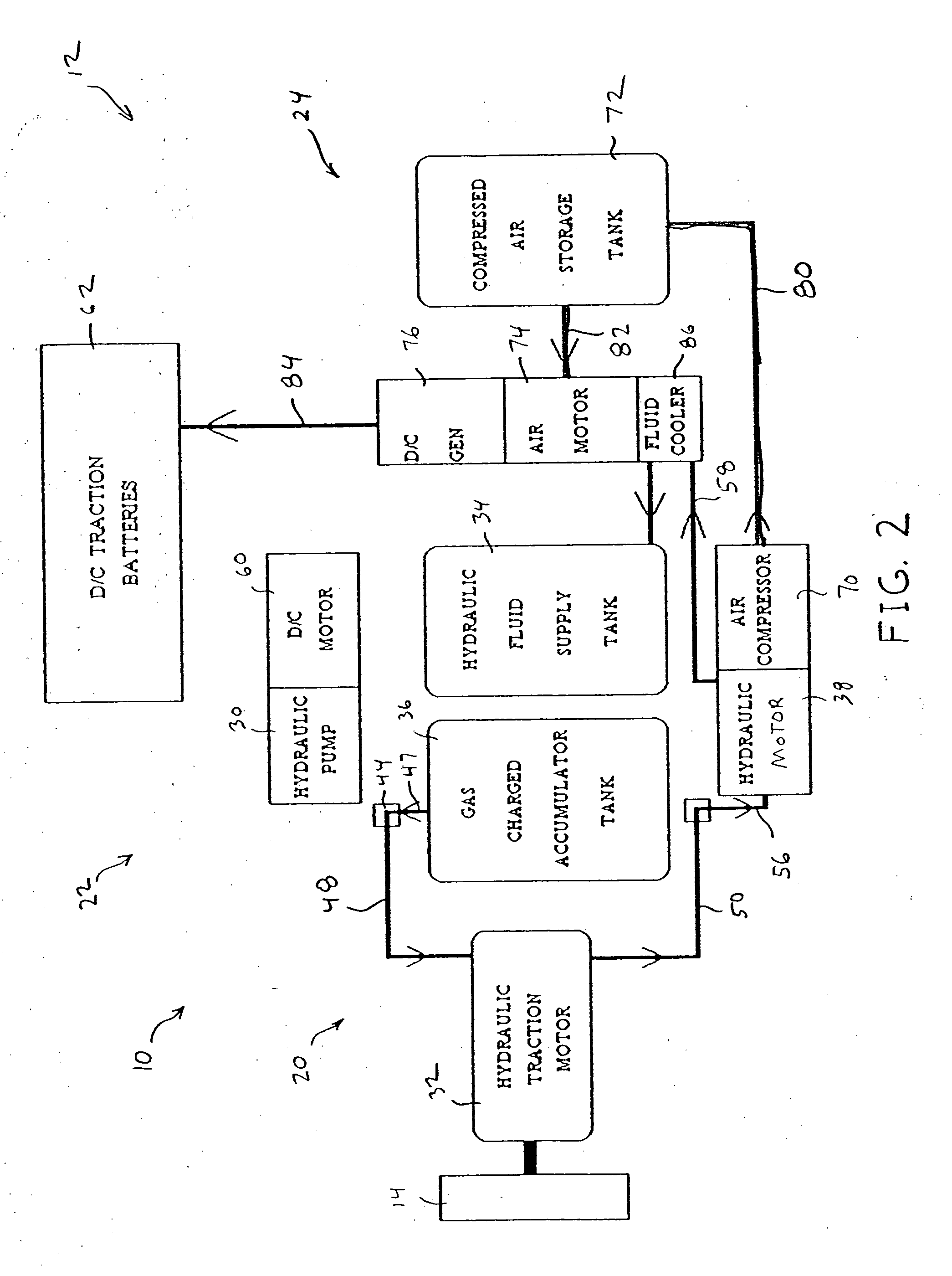
[0044] Referring now to FIG. 1, a fluid drive system generally indicated as 10 is used to drive or propel a vehicle generally indicated as 12, which has a drive wheel 14. Drive system 10 has energy regeneration and storage capabilities and includes fluid or hydraulic components generally indicated as 20, electrical energy supply and drive components generally indicated as 22, and an electrical regeneration system generally indicated ...


PUM


Abstract

A fluid drive system that can be used to drive a vehicle and has energy regeneration and storage capabilities. The fluid drive system includes an electrical energy supply source mounted on the vehicle, at least one electrical motor electrically connected to the electrical supply source, and a hydraulic pump driven that may be of the variable displacement type by the electrical motor. The fluid drive system may also include a low pressure hydraulic fluid supply tank supplying fluid to the hydraulic pump, at least one pneumatically charged accumulator tank for storing pressurized hydraulic fluid, a combination hydraulic motor and pump that may also be of the variable displacement type being alternately driven by the hydraulic pump and the pneumatically charged accumulator tank; and an electrical regeneration system for regenerating the electrical energy supply. The electrical regeneration system may be powered by hydraulic fluid from the combination electrical motor and pump. The combination hydraulic motor and pump propels the vehicle during acceleration and speed maintaining operations and may also serves as a braking mechanism during deceleration of the vehicle. The combination hydraulic motor and pump may also pump hydraulic fluid into the pneumatically charged accumulator tank during at least a portion of the time that the vehicle is decelerating. The combination hydraulic motor and pump may further pump hydraulic fluid for powering the electrical regeneration system when the pneumatically charged accumulator tank is fully pressurized. The electrical regeneration system also has the ability to recharge the electrical energy supply while the vehicle is stopped using stored recovered kinetic energy.

Description

[0001] This application claims the benefit of U.S. Provisional Patent Application Ser. No. 60 / 545,051 filed Feb. 17, 2004, the complete disclosure of which is hereby expressly incorporated by reference.BACKGROUND OF THE INVENTION [0002] This invention relates to a fluid drive system for a vehicle, and in particular to a fluid drive system having energy regeneration and storage capabilities. This system employs existing technology and a novel arrangement that in one embodiment provides both hydraulic and pneumatic systems, which extract kinetic energy from the vehicle as it is decelerating or braking. The system converts the kinetic energy to both stored pressurized hydraulic fluid and to stored electrical energy, which both can be used to power the fluid drive system. [0003] In an effort to conserve resources and reduce environmental impact, numerous vehicles and drive systems have been developed including electrical vehicles, hydraulic vehicles, and hybrid vehicles which use a comb...

Claims


Application Information

Patent Timeline
Patent Type & Authority Applications(United States)
IPC IPC(8): B60K6/12F16D31/00
CPCB60K6/12B60T2270/604Y02T10/6208Y02T10/92B60L3/0061Y02T10/7005B60L11/1805B60L2240/12B60L2240/36B60L2200/26B60L7/12B60L50/52Y02T10/62Y02T10/70
Inventor HUGHEY, CHARLES E.
Owner PARKER I L L C
Why Eureka
Try Eureka