Apparatus and method for producing a glass optical element and glass optical element produced thereby

a technology of glass optical elements and apparatuses, which is applied in glass tempering apparatuses, glass making apparatuses, manufacturing tools, etc., can solve the problems of gas escaping from the space, the above-mentioned methods are disadvantageous, and the optical performance and surface quality of the optical element obtained by press-forming are adversely affected, so as to achieve efficient heat and heat soak the glass material

Active Publication Date: 2005-08-18
HOYA CORP
View PDF2 Cites 28 Cited by
  • Summary
  • Abstract
  • Description
  • Claims
  • Application Information

AI Technical Summary

Benefits of technology

[0033] With the above-mentioned method, it is possible to reliably produce an optical element high in accuracy without a gas trap mark.
[0034] A glass optical element according to this invention may be an objective lens having a numerical aperture NA of 0.7 or more and a total wavefront aberration WFE of 0.06 λrms at a usable wavelength of 380-450 nm.
[0035] According to this invention, there is provided a glass optical element having a first surface and a second surface as curved surfaces, the glass optical element having a volume V and satisfying the relationship RM′ / RL>1.0 where RL represents a paraxial radius of curvature of the first or the second surface and RM′ is a value satisfying (4 / 3)π(RM′)3=V, wherein a gas trap mark which may be formed in the vicinity of a surface of the glass optical element is not greater in diameter than 200 μm.
[0036] The above-mentioned glass optical element does not have the gas trap mark degrading optical performance and, therefore, can be used as a high-accuracy objective lens for use with an optical information recording medium to record or reproduce information.
[0037] As described above, by the method of producing a glass optical element according to this invention, it is possible to discharge the trapped gas from the space formed between the glass material and the forming mold and to hermetically seal the space thereafter without adversely affecting the shape of the glass optical element. Moreover, it is possible to efficiently heat and heat-soak the glass material in the atmospheric gas.

Problems solved by technology

In case where the glass materials of these shapes are used to form optical elements, there may arise a problem which will presently be described.
As a result, optical performance and surface quality of the optical element obtained by press-forming are adversely affected.
However, the above-mentioned methods are disadvantageous in the following respects.
In this method, however, the gas tends to remain trapped in the space depending upon the shape or the volume of the space.
In addition, mold release at a press-forming temperature may cause glass fusion or defective appearance of an optical element obtained by press-forming.
In this method, however, it is impossible to utilize heat conduction through an atmospheric gas in the forming chamber as a medium in order to heat the forming die and the preform because the forming chamber is evacuated into vacuum.
As a result, heating efficiency is insufficient.
In addition, heat-soaking to bring the die and the preform to uniform temperature is difficult and temperature control is unstable.
As a result, the glass material has a low viscosity and is inevitably deformed to trap the gas between the glass material and the lower die after the glass material is transferred.
Therefore, the gas can not be purged or removed even if pressure reduction is performed thereafter.
Thus, in the above-mentioned conventional methods described in References 1 to 4, it is impossible to completely purge the gas from the space between the forming mold and the preform.

Method used


Image

  • Apparatus and method for producing a glass optical element and glass optical element produced thereby
  • Apparatus and method for producing a glass optical element and glass optical element produced thereby
  • Apparatus and method for producing a glass optical element and glass optical element produced thereby

Examples


first example

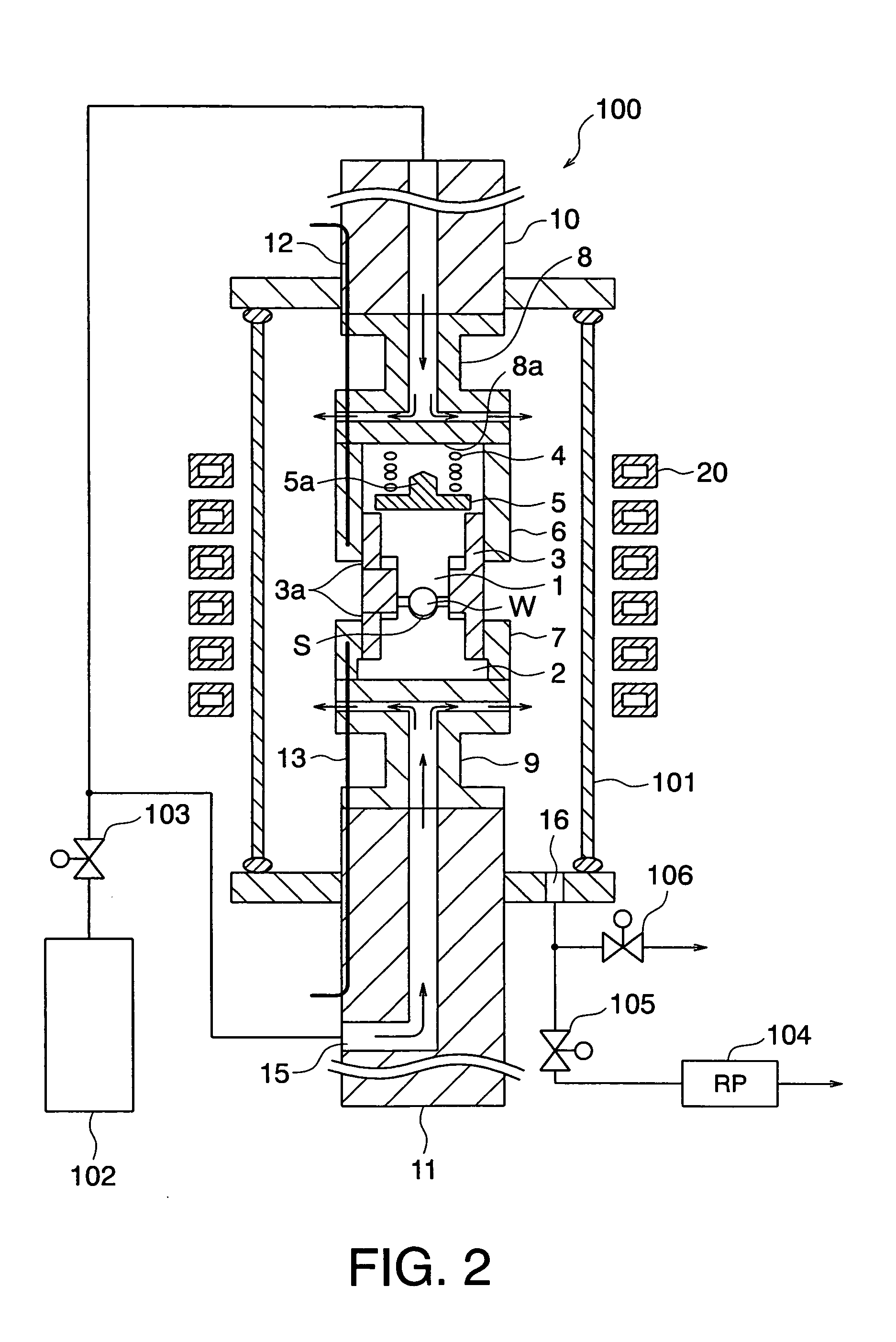
[0095] Description will be made of a first example using the apparatus illustrated in FIG. 2.

[0096]FIG. 3 shows a press schedule in the first example.

[0097] In this example, the glass material W had a spherical shape and was produced by polishing an optical glass material having nd=1.69350, vd=53.20, a sagging point of 560° C., and a transition point of 520° C. into a diameter of 2.7 mm.

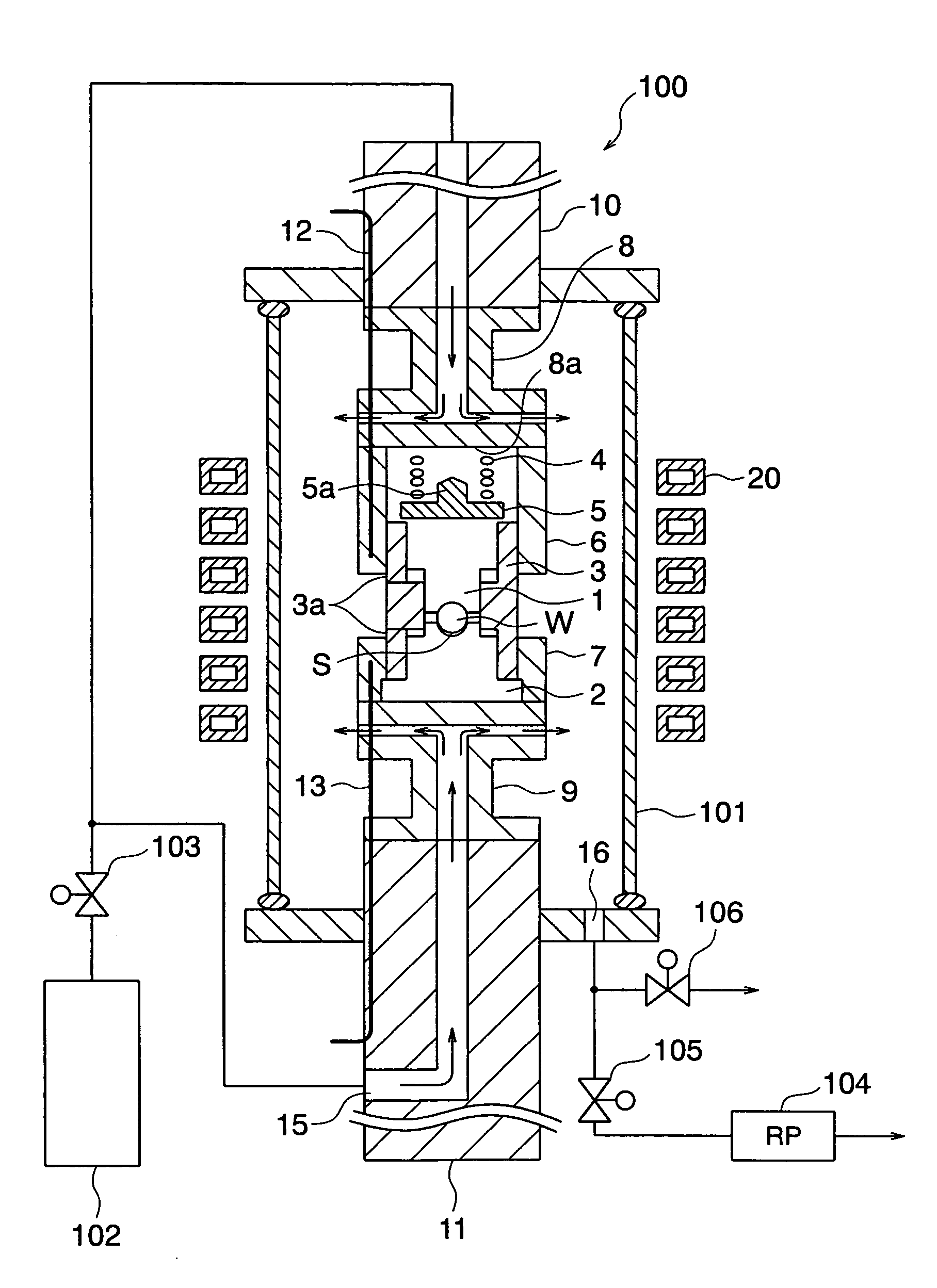
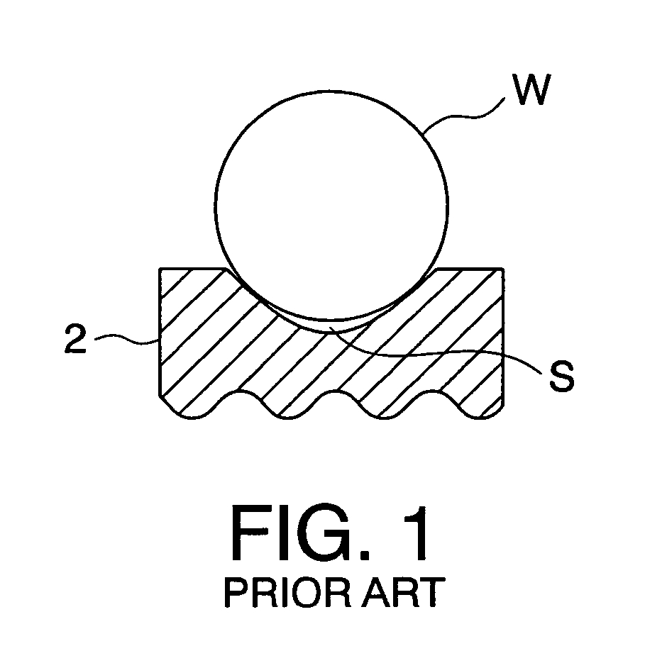
[0098] The glass material W was placed on the forming surface of the lower die 2. The forming surface had a paraxial radius of curvature of 1.1 mm. Next, the upper die 1 and the sleeve 3 were set. The space S was formed between the lower die 2 and the glass material W. The maximum height of the space S at the center was 75 μm. In FIG. 2, the size of the space S is emphasized for convenience of illustration.

[0099] A contacting portion at which the lower die 2 and the glass material W were contacted with each other had a diameter of 2.2 mm. The optical element (lens) after press-forming had an oute...

second example

[0114] Hereinafter, description will be made of a second example using the apparatus illustrated in FIG. 4.

[0115]FIG. 5 shows a press schedule in the second example.

[0116] The species of the glass material and the shapes of the optical element (lens) and the forming mold are same as those in the first example.

[0117] A pressing process in the second example is as follows.

[0118] Using a die assembling / disassembling unit (not shown), the glass material W was placed on the lower die 2. Next, the upper die 1 was inserted into the sleeve 3. The forming mold comprising the upper and the lower dies 1 and 2 was put on a die support 17 and loaded into the preliminary chamber (not shown) adjacent to the heating furnace chamber 101b. After evacuation, the nitrogen gas was introduced into the preliminary chamber to perform gas exchange. After completion of gas exchange into the nitrogen gas, the shutter 112 was opened. The forming mold together with the die support 17 was transferred into th...


PUM

PropertyMeasurementUnit
glass viscosityaaaaaaaaaa
diameteraaaaaaaaaa

Abstract

In a method of manufacturing a glass optical element by press-forming a glass material in a chamber by using a forming mold comprising upper and lower dies at least one of which is movable, where a surrounded space is formed between the glass material and at least one of the upper and the lower dies when the upper and the lower dies come into contact with the glass material, a pressure within the chamber is reduced before the glass material placed in the forming mold is heated to a press-forming temperature. After sealing the space as formed when the glass material is in contact with at least one of forming surfaces of the upper and the lower dies, a gas is introduced into the chamber. The glass material is heated in the gas and then press-formed under a pressing load.

Description

[0001] This invention claims priority to prior Japanese patent application JP 2004-34504, the disclosure of which is incorporated herein by reference. BACKGROUND OF THE INVENTION [0002] This invention relates to a method and an apparatus for producing an optical element, such as a lens, made of an optical glass and, in particular, to a method and an apparatus for producing a glass optical element by press-forming or press-molding a heated and softened glass material with high accuracy using a forming mold or die precisely shaped in conformity with a desired shape of the optical element. This invention also relates to a glass optical element produced by the method and the apparatus. [0003] In order to produce an optical element, such as an optical glass lens, for use in an optical apparatus such as a camera and an optical pickup, proposal has recently been made of a number of methods in which a heated and softened glass material is press-formed or press-molded by the use of a forming...

Claims


Application Information

Patent Timeline
Patent Type & Authority Applications(United States)
IPC IPC(8): C03B11/00C03B11/06C03B11/08C03B11/12C03B23/00
CPCC03B11/005C03B11/08C03B11/125C03B2215/72C03B2215/66C03B2215/69C03B2215/65
Inventor YONEDA, YASUHIRO
Owner HOYA CORP
Why Eureka
Try Eureka