Cable traction apparatus and method
a cable traction and cable technology, applied in the direction of rope railways, hoisting equipment, transportation and packaging, etc., can solve the problems of 0.7 and is generally not able to be dramatically increased, and achieve the effect of high force, reduced number of parts required, and high normal for
- Summary
- Abstract
- Description
- Claims
- Application Information
AI Technical Summary
Benefits of technology
Problems solved by technology
Method used
Image
Examples
Embodiment Construction
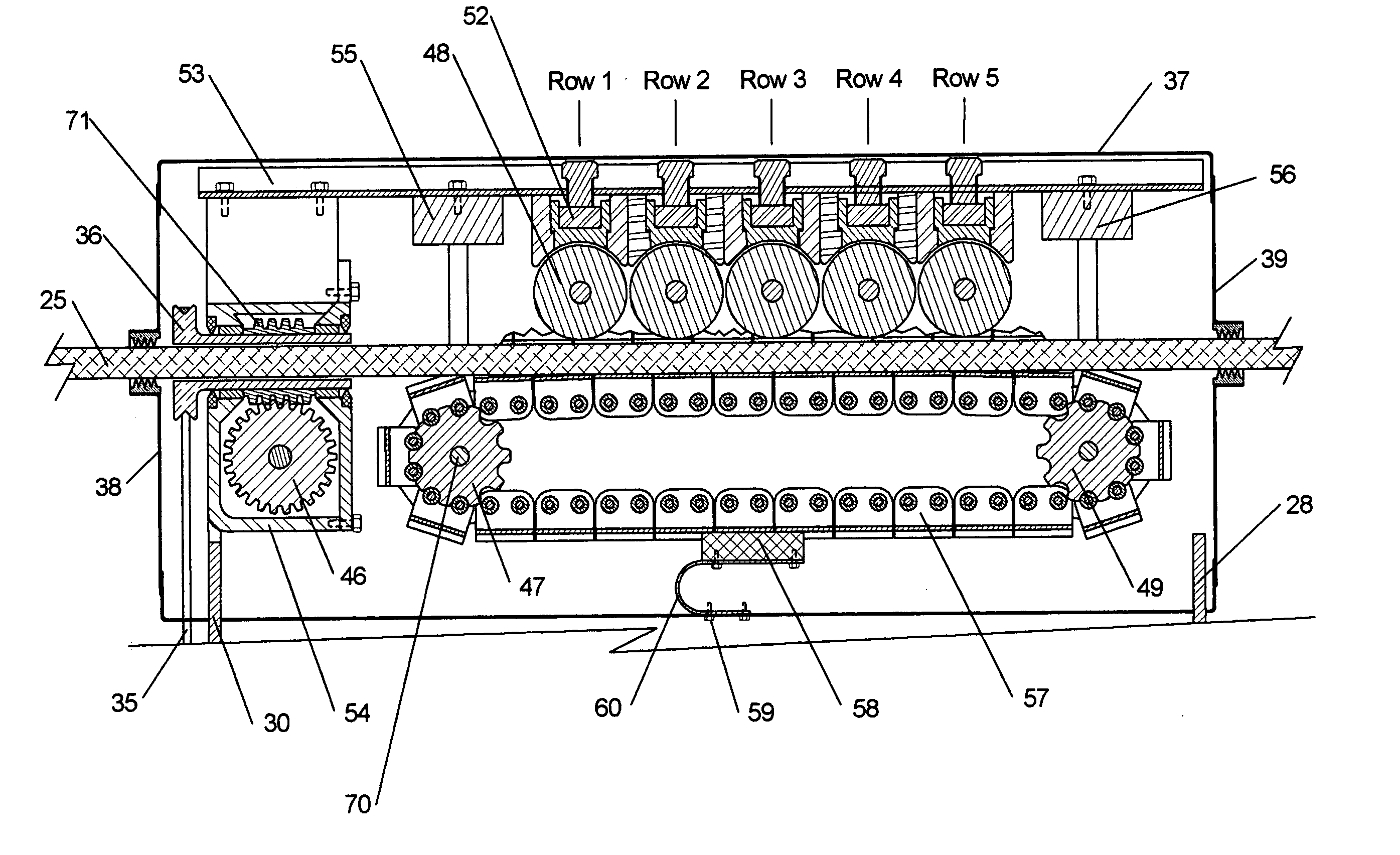
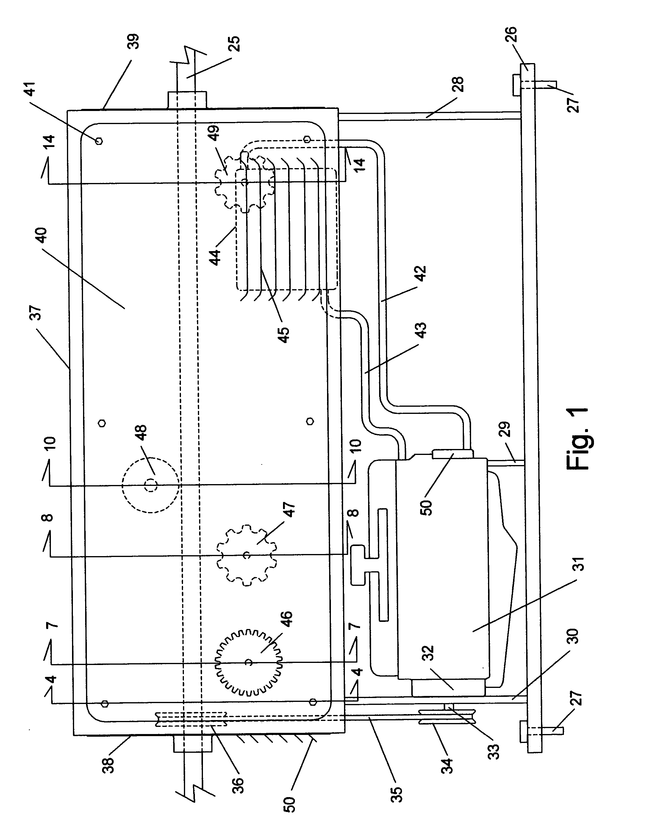
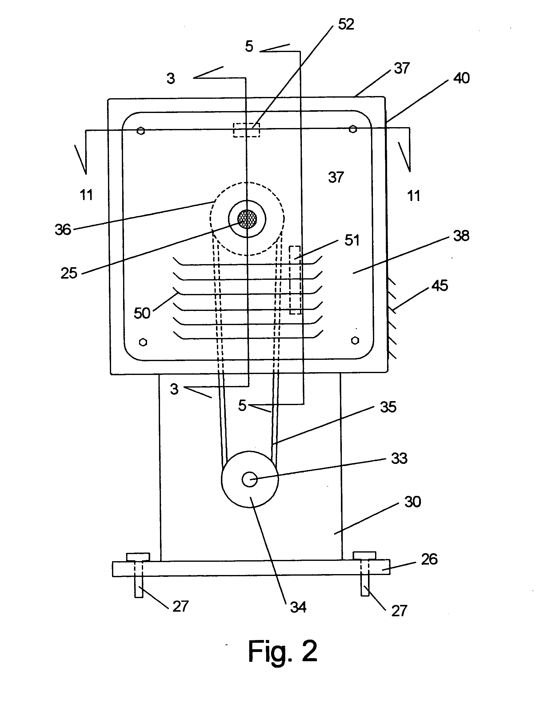
[0043]FIG. 1 shows the side view of the cable traction apparatus. The cable 25 enters and passes through the cable traction apparatus in a straight line. This cable could typically be a steel wire rope such as the AISI (American Iron and Steel Institute) standard 6×27H flattened strand (3 wire center) IWRC (independent wire-rope core) shown in FIG. 15. A cable is frequently mentioned, however the apparatus would provide traction to any reasonably rigid and reasonably constant cross section elongate member. Examples of this could include pipe, hose, dowel, or rope. Other non-circular cross sections would include a box-beam or hex-pipe. For a non-circular cross section, the cable link 86, shown in FIG. 8, would be shaped to match. The elongate member materials could include steel, aluminum, wood, copper and various multi-layer constructions. These shape and material examples are only representative and there are many others.
[0044] The base 26 provides support for the various mechanis...
PUM
 Abstract
Description
Claims
Application Information
 - R&D
- Intellectual Property
- Life Sciences
- Materials
- Tech Scout
- Unparalleled Data Quality
- Higher Quality Content
- 60% Fewer Hallucinations
Browse by: Latest US Patents, China's latest patents, Technical Efficacy Thesaurus, Application Domain, Technology Topic, Popular Technical Reports.
© 2025 PatSnap. All rights reserved.Legal|Privacy policy|Modern Slavery Act Transparency Statement|Sitemap|About US| Contact US: help@patsnap.com


