
Spine folded portion flattening apparatus, sheet treating apparatus and image forming apparatus

Active Publication Date: 2005-08-18
CANON KK
View PDF30 Cites 77 Cited by
  • Summary
  • Abstract
  • Description
  • Claims
  • Application Information

AI Technical Summary

Benefits of technology

[0014] It is an object of the present invention to provide a spine folded portion flattening apparatus enhanced in the flattening process efficiency of moving a sheet bundle and flattening the spine folded portion thereof.
[0015] It is an object of the present invention to provide a sheet treating apparatus provided with a spine folded portion flattening apparatus enhanced in the process efficiency of flattening the spine folded portion of a sheet bundle, and enhanced in sheet treating efficiency.
[0016] It is an object of the present invention to provide an image forming apparatus provided with a spine folded portion flattening apparatus enhanced in the process efficiency of flattening the spine folded portion of a sheet bundle, and enhanced in the efficiency of forming an image on a sheet.
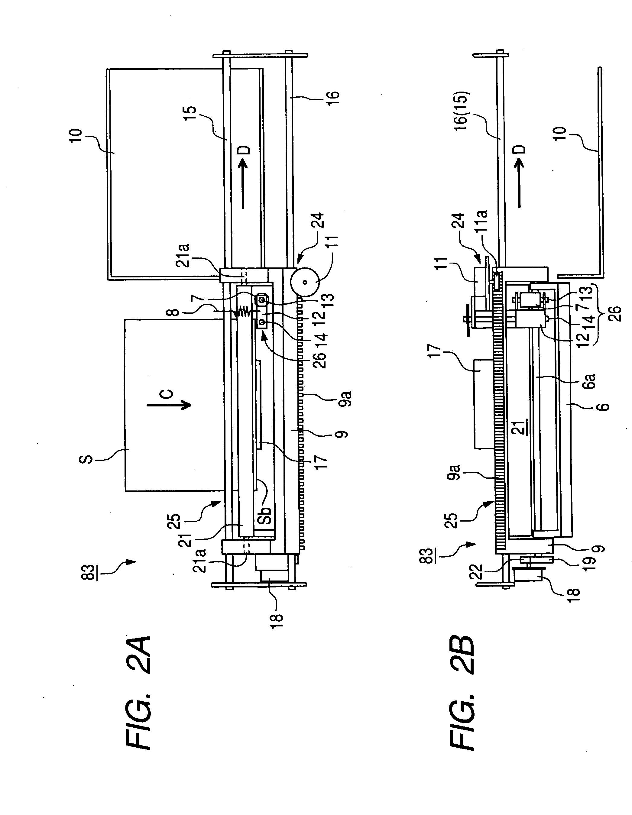
[0020] The spine folded portion flattening apparatus of the present invention is adapted to press and flatten the spine folded portion of a sheet bundle by the pressing portion while moving the sheet bundle by the sheet bundle moving device and therefore, can flatten the spine folded portion without stopping the sheet bundle, thus enhancing the spine folded portion flattening process efficiency.
[0021] The sheet treating apparatus of the present invention is provided with the spine folded portion flattening apparatus enhanced in the spine folded portion flattening process efficiency and therefore, can enhance the sheet treating efficiency of the entire sheet treating apparatus.
[0022] The image forming apparatus of the present invention is provided with the spine folded portion flattening apparatus enhanced in the spine folded portion flattening process efficiency and therefore, can enhance the image forming efficiency of the entire image forming apparatus.

Problems solved by technology

Such sheet bundles, when piled, assume an unstable state, and has been liable to get out of shape and difficult to keep storing in a piled state or transport.
Therefore, the conventional spine folded portion flattening apparatus 101 has been poor in the efficiency of the spine folded portion flattening process correspondingly to the time for which the conveyance of the sheet bundle S is stopped.
Also, the conventional sheet treating apparatus is provided with the spine folded portion flattening apparatus poor in the process efficiency as described above and therefore, under the influence of the process efficiency of the spine folded portion flattening apparatus, it has been poor in the sheet treating efficiency as the entire sheet treating apparatus.
Further, the conventional image forming apparatus is provided with the spine folded portion flattening apparatus which is poor in the process efficiency of flattening the spine folded portion and therefore, under the influence of the process efficiency of the spine folded portion flattening apparatus, it has been poor in the image forming efficiency as the entire image forming apparatus.

Method used


Image

  • Spine folded portion flattening apparatus, sheet treating apparatus and image forming apparatus
  • Spine folded portion flattening apparatus, sheet treating apparatus and image forming apparatus
  • Spine folded portion flattening apparatus, sheet treating apparatus and image forming apparatus

Examples


second embodiment

Spine folded portion Flattening Apparatus

Description of the Construction of the Spine Folded Portion Flattening Apparatus According to the Second Embodiment

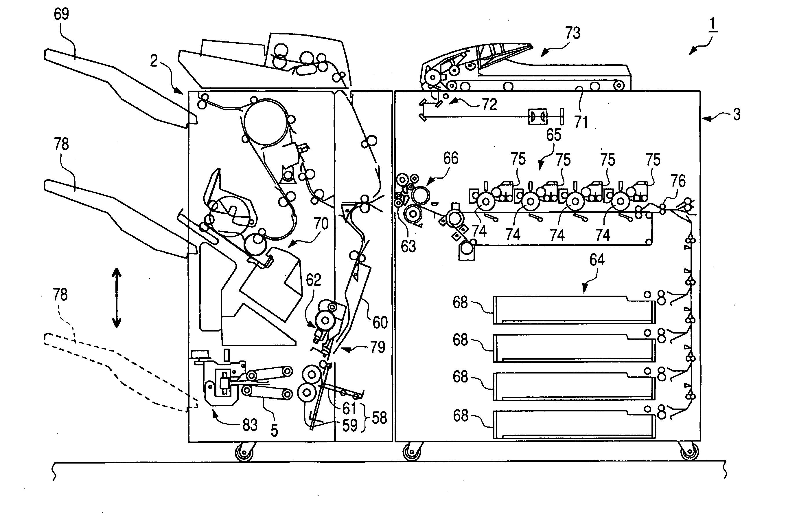
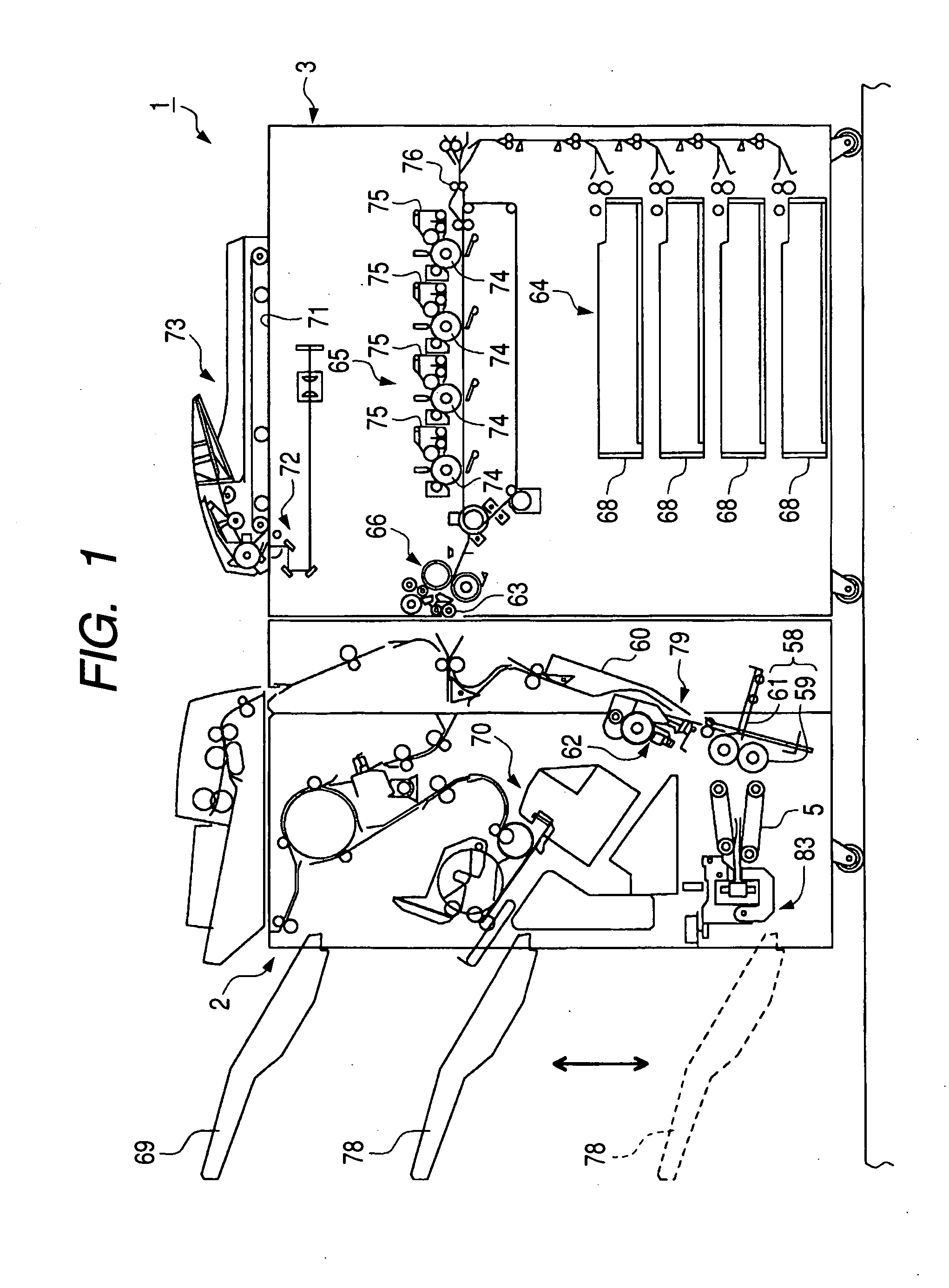
[0079] As shown in FIGS. 8A, 8B and 9 to 11, the spine folded portion flattening apparatus 84 according to the second embodiment is also adapted to flatten the U-shaped curved spine folded portion (spine cover) Sb of a folio pamphlet-shaped sheet bundle sent thereto from the pamphlet making apparatus 79.

[0080] The spine folded portion flattening apparatus 84 according to the second embodiment differs in the construction of the gripping apparatus from the spine folded portion flattening apparatus 83 according to the first embodiment. That is, the gripping device 23 of the spine folded portion flattening apparatus 83 according to the first embodiment uses a pair of grippers 6 and 21, whereas the sheet gripping apparatus 88 of the spine folded portion flattening apparatus 84 according to the second embodiment uses a drive conveyin...

third embodiment

Spine Folded Portion Flattening Apparatus

Description of the Construction of the Spine Folded Portion Flattening Apparatus According to the Third Embodiment

[0093] As shown in FIGS. 12A and 12B, the spine folded portion flattening apparatus 85 according to the third embodiment is also adapted to flatten the U-shaped curved spine folded portion (spine) Sb of a folio pamphlet-shaped sheet bundle sent thereto from the pamphlet making apparatus 79.

[0094] The spine folded portion flattening apparatus 85 according to the third embodiment differs in the construction of the gripping apparatus from the spine folded portion flattening apparatus 83 according to the first embodiment. That is, the gripping device 23 of the spine folded portion flattening apparatus 83 according to the first embodiment uses a pair of grippers 6 and 21, whereas the gripping device 91 of the spine folded portion flattening apparatus 85 according to the third embodiment uses a drive conveying roller 81 and a driven c...


PUM

PropertyMeasurementUnit
Lengthaaaaaaaaaa

Abstract

A sheet bundle spine folded portion flattening apparatus is provided with a conveying portion which conveys the folded sheet bundle with the spine folded portion of the folded sheet bundle at a head, a sheet bundle moving device for moving it in a direction along the spine folded portion of the sheet bundle, and a pressing device for pressing the spine folded portion of the sheet bundle being moved by the sheet bundle moving device, and is adapted to press and flatten the spine folded portion of the sheet bundle being moved by the sheet bundle moving device, by the pressing device and therefore, can flatten the spine folded portion almost without stopping the movement of the sheet bundle, as compared with the conventional art, and the sheet bundle treating efficiency is enhanced.

Description

BACKGROUND OF THE INVENTION [0001] 1. Field of the Invention [0002] The invention relates to a spine folded portion flattening apparatus for flattening the curved spine folded portion of a folded sheet bundle, and particularly flattening the spine folded portion while moving the sheet bundle, a sheet treating apparatus and an image forming apparatus provided with the same. [0003] 2. Related Background Art [0004] Heretofore, a predetermined number of sheets, e.g. about 20 or fewer sheets have been stacked one upon another and have been folded into the form of a pamphlet by a suture / folding machine. As the sheet bundle folded by such a suture / folding machine, there is a simply folded sheet bundle, a saddle-stitched and folded sheet bundle, a sheet bundle not bound by yarn or staple but bound by an adhesive (perfect binding) and folded, or the like. [0005] However, any of these sheet bundles has more or less elastic force and therefore, after it has been folded, the periphery of a spin...

Claims


Application Information

Patent Timeline
IPC IPC(8): B42C19/00B42C5/00B42C5/02
CPCB42C5/02B65H2701/13212B65H2301/51232B65H45/18
Inventor KAMIYA, DAISAKUOBUCHI, YUSUKEFUJIMOTO, HITOSHIWATANABE, KIYOSHINAKAMURA, TOMOKAZUHAYASHI, KENICHISUZUKI, TOSHIMASAKUSHIDA, HIDEKIOIKAWA, ATSUTERU
Owner CANON KK
Learn More