Recording medium feed device

a technology of feed device and recording medium, which is applied in the direction of transportation and packaging, article separation, thin material processing, etc., can solve the problems of increasing costs, and achieve the effect of preventing the loading of recording medium

Inactive Publication Date: 2005-08-18
KONICA MINOLTA BUSINESS TECH INC
View PDF2 Cites 24 Cited by
  • Summary
  • Abstract
  • Description
  • Claims
  • Application Information

AI Technical Summary

Benefits of technology

[0014] The present invention is made in view of the above problems, and an object thereof is to provide a recording medium feed device which includes an installable and removable recording medium feed tray, has a simple structure that suppresses a cost increase, and prevents “no feed.”
[0015] As described above, the inventors of the present invention have found out during their study on a recording medium feed device that, in a structure where the send-out roller is always in contact with the recording media, “no feed” can be prevented even when a wavy recording medium such as backside paper is used, since the send-out roller is always in contact with the recording media and thus no gap is formed between the recording media. However, in a structure where the recording medium feed tray and the recording medium feed unit are integral with each other, cost is increased even though it is easy to allow the send-out roller to be always in contact with the paper.
[0016] The present invention has been achieved on the idea that cost can be suppressed and “no feed” can be prevented by separating the recording medium feed tray and the recording medium feed unit, and bringing the send-out roller into contact with the top face of the recording media at the time of installing the recording medium feed tray, while withdrawing the send-out roller from the top face of the recording media at the time of removing the recording medium feed tray in order not to displace the recording media loaded in the recording medium feed tray.
[0020] Moreover, by withdrawing the send-out member from the top face of the recording medium in the recording medium feed tray at the time of removing the recording medium feed tray, it is possible to prevent the recording medium from being displaced. Thus, the recording medium can be prevented from being torn or defectively conveyed.
[0023] Moreover, by withdrawing the send-out roller from the top face of the recording medium in the recording medium feed tray at the time of removing the recording medium feed tray, it is possible to prevent the recording medium from being displaced. Thus, the recording medium can be prevented from being torn or defectively conveyed.
[0025] By providing the recording medium holding member to be in contact with the top face of the recording medium in the recording medium feed tray only at a time of removing the recording medium feed tray, the recording medium holding member being formed integrally with the send-out roller, the send-out roller is prevented from contacting with the recording medium. Accordingly, it is possible to prevent the recording medium loaded in the recording medium feed tray from being displaced.

Problems solved by technology

However, in a structure where the recording medium feed tray and the recording medium feed unit are integral with each other, cost is increased even though it is easy to allow the send-out roller to be always in contact with the paper.

Method used


Image

  • Recording medium feed device
  • Recording medium feed device
  • Recording medium feed device

Examples


Embodiment Construction

[0034] Hereinbelow, an embodiment of the present invention will be described. Note that the definitive descriptions given hereinbelow only show a best mode of the invention, and thus should not be taken as limiting in any way the definitions of the terms of the invention or the technical scope of the invention.

[0035] First, with reference to FIG. 1, a description will be given of an embodiment of an image forming apparatus having a recording medium feed device according to the present invention.

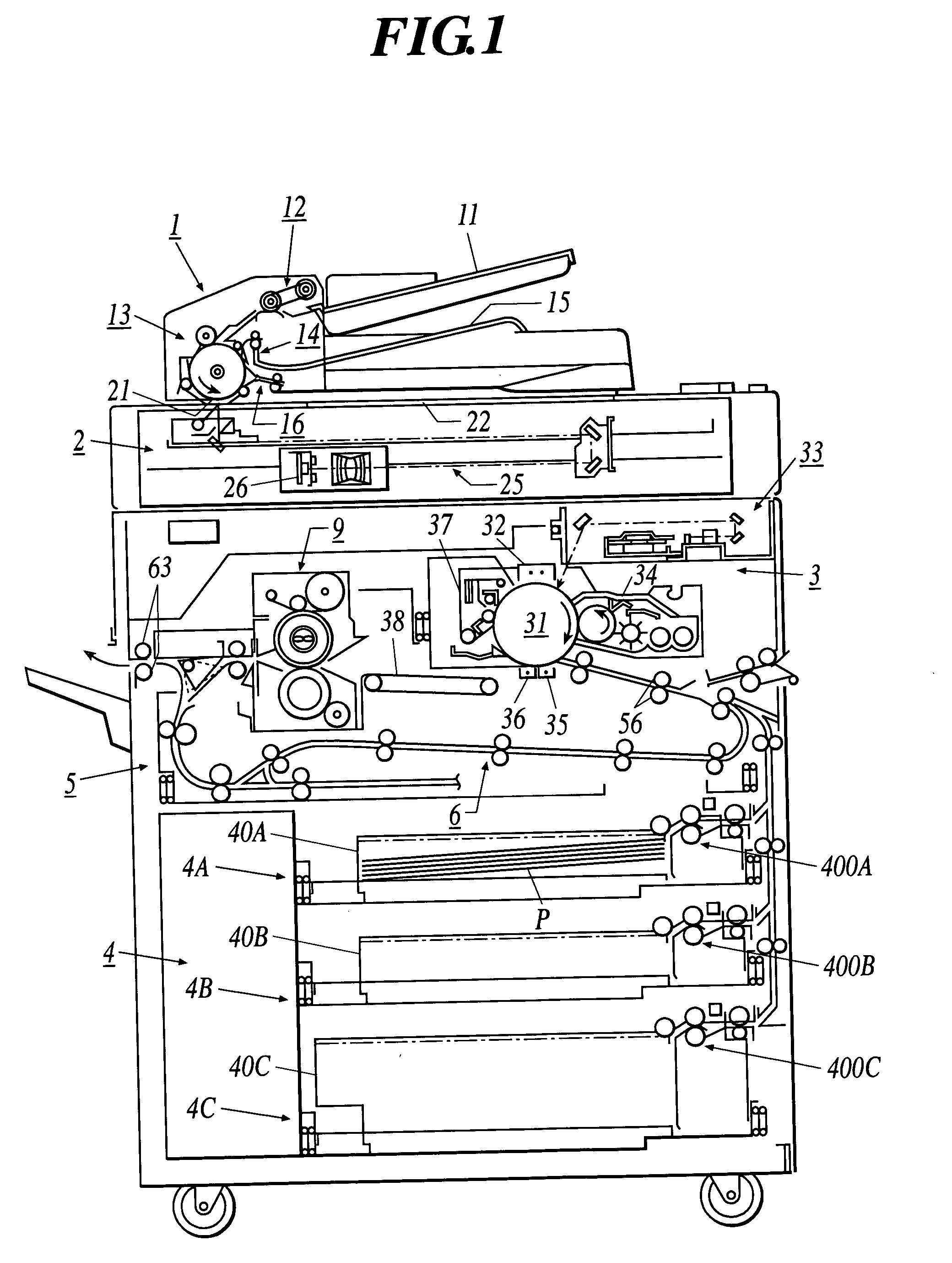
[0036]FIG. 1 is a schematic view showing a structure of an image forming apparatus as a digital copying machine.

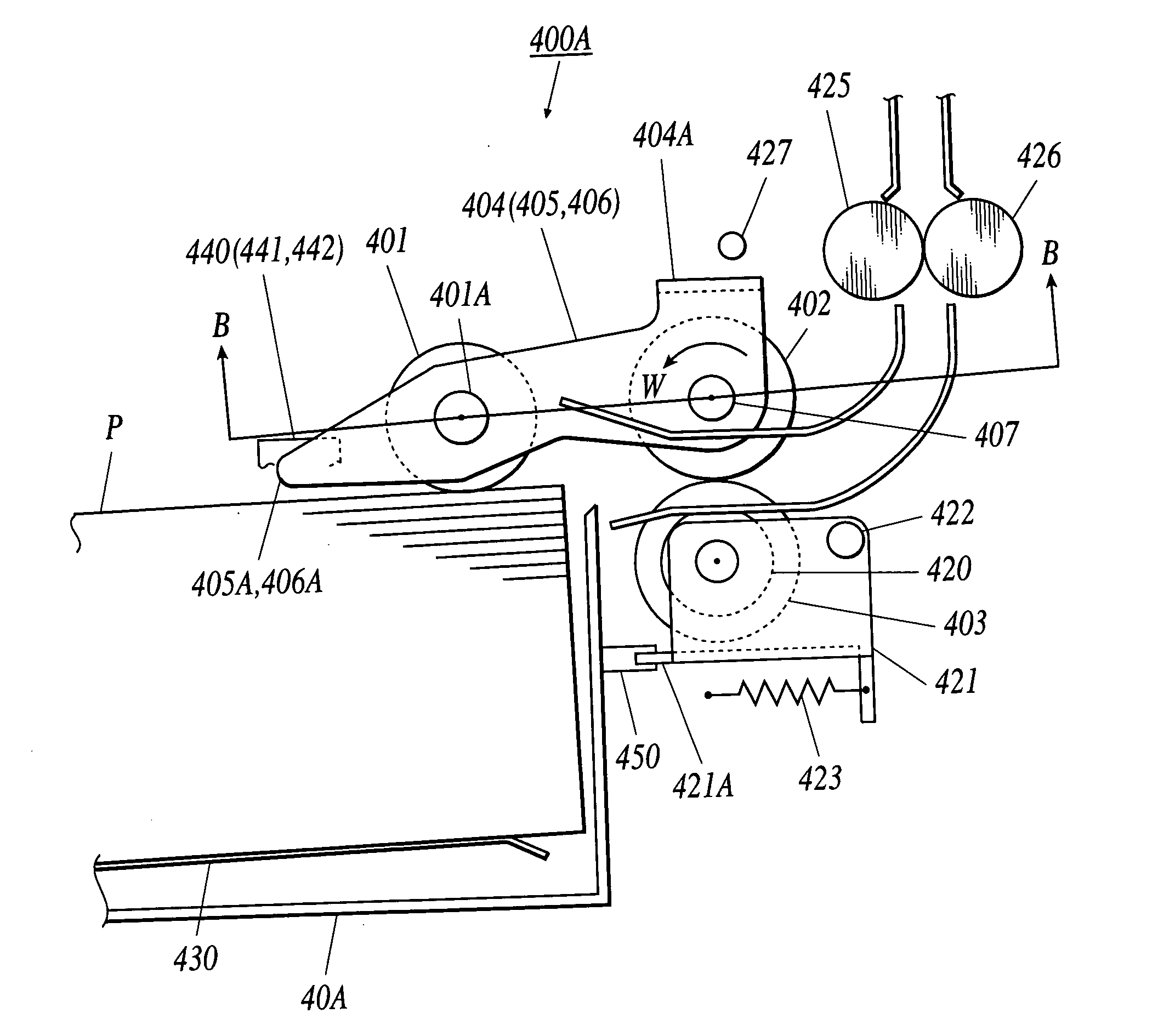
[0037] The image forming apparatus according to this embodiment forms a toner image on a recording medium by using an electrophotographic method. The image forming apparatus includes: an automatic original feed device 1; an image reading device 2; an image forming section 3; a recording medium feed section 4; a reversed recording medium discharging and re-feeding section 5; and a...


PUM


Abstract

A recording medium feed device includes: a recording medium feed tray installable to and removable from a main body of the recording medium feed device; a send-out member to send out a recording medium loaded in the recording medium feed tray, the send-out member being in contact with a top face of the recording medium while applying pressure thereto at a time of installing the recording medium feed tray; and a withdrawing mechanism to withdraw the send-out member from the top face of the recording medium in the recording medium feed tray at a time of removing the recording medium feed tray.

Description

BACKGROUND OF THE INVENTION [0001] 1. Field of the Invention [0002] The present invention relates to a recording medium feed device which is installed in an image forming apparatus such as a copying machine, a printer or a printing press, a paper post-processing apparatus, and the like. [0003] 2. Description of the Related Art [0004] As a recording medium feed device used in an image forming apparatus or the like, a device as shown in FIG. 7 has been known (for example, see JP-Tokukaihei-7-144771A). [0005] In FIG. 7, reference numeral 101 denotes a recording medium feed roller, reference numeral 102 denotes a separating roller to be in contact with the recording medium feed roller 101 and connected to a torque limiter (not shown), and reference numeral 103 denotes a send-out roller swingably supported on the rotary shaft of the recording medium feed roller 101. [0006] Reference numeral 104 denotes a pick-up cam which brings the send-out roller 103 into contact with paper. P loaded t...

Claims


Application Information

Patent Timeline
Patent Type & Authority Applications(United States)
IPC IPC(8): B65H1/26B65H3/06B65H3/52
CPCB65H3/06B65H3/5261B65H2403/513B65H2404/1442B65H2404/1521B65H2405/32B65H2511/20B65H2220/01B65H2220/02B65H2220/11B65H2220/08
Inventor MIURA, KAZUNOBUKAWABATA, SHINICHINONAKA, KENKAWACHI, KUNIHIROMIZUNO, KYOICHI
Owner KONICA MINOLTA BUSINESS TECH INC
Why Eureka
Try Eureka