Motor for electric power steering apparatus

Active Publication Date: 2005-08-18
MITSUBISHI ELECTRIC CORP
View PDF4 Cites 38 Cited by
  • Summary
  • Abstract
  • Description
  • Claims
  • Application Information

AI Technical Summary

Benefits of technology

[0007] Accordingly, the present invention is intended to obviate the above-mentioned various problems, and has for its object to provide a motor for an electric power steering apparatus in which working e

Problems solved by technology

In such a known motor for an electric power steering apparatus, the lead-side terminals are connected through welding with the connection portion of the stator-side terminal, and hence there arises a problem that connection work is troublesome and assemblability is poor.
In addition, for example, in cases where some defect is found upon inspection after as

Method used


Image

  • Motor for electric power steering apparatus
  • Motor for electric power steering apparatus
  • Motor for electric power steering apparatus

Examples


embodiment 1

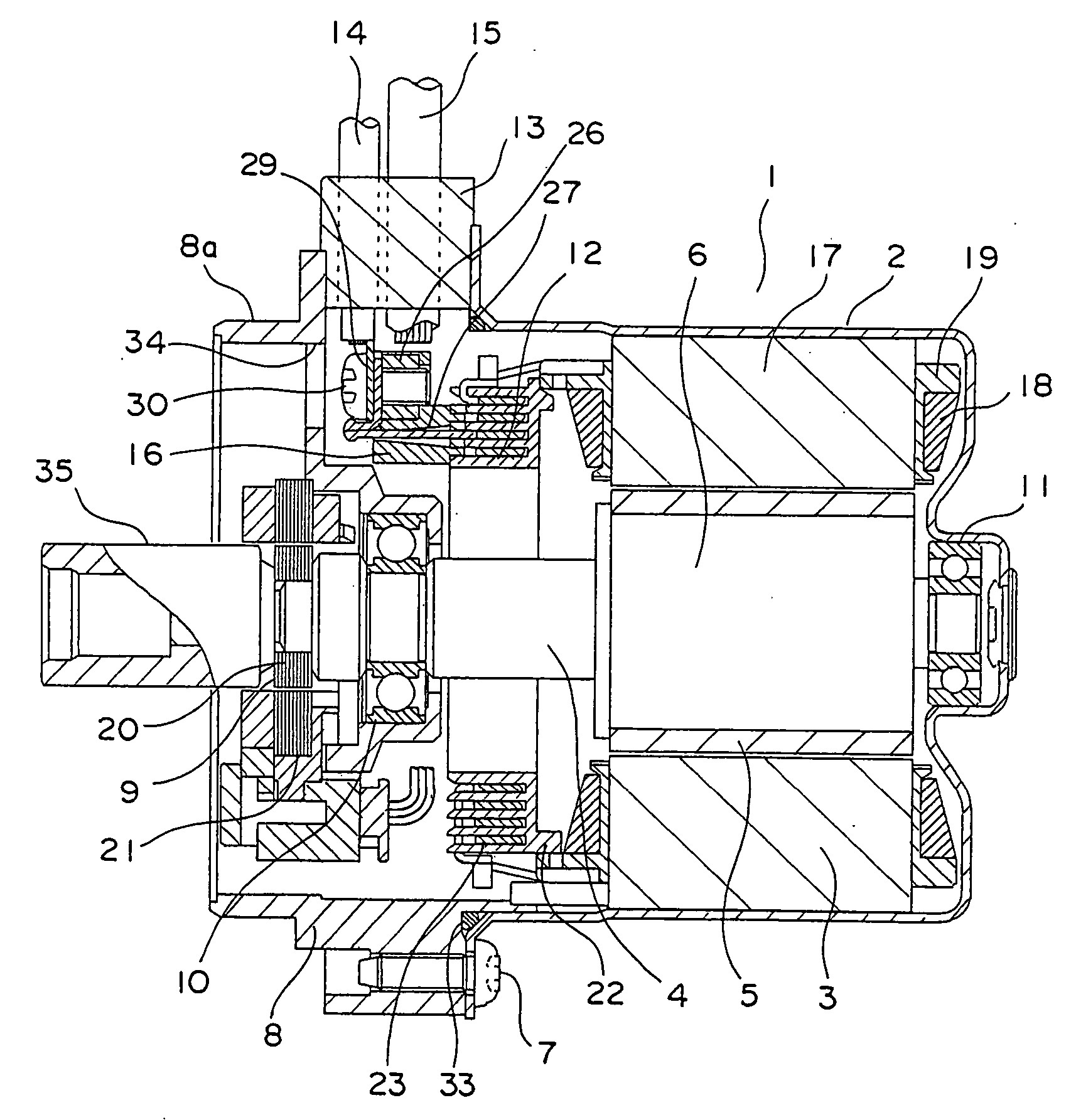
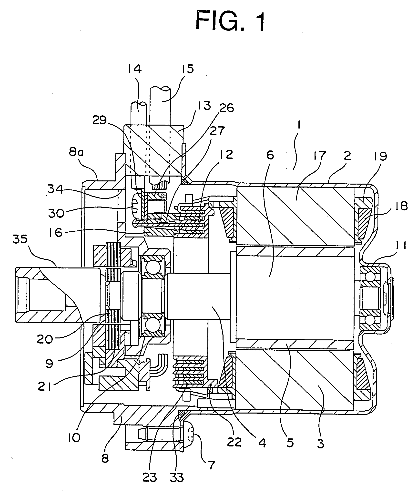
[0036]FIG. 1 is a cross sectional side view of a motor 1 for an electric power steering apparatus (hereinafter simply referred to as “motor”). FIG. 2 is a front elevational view of the motor 1 of FIG. 1. FIG. 3 is a partial perspective front elevational view of FIG. 2. FIG. 4 is a disassembled view of the motor 1 of FIG. 1. FIG. 5 is a side elevational view of the motor 1.

[0037] The motor 1 includes a bottomed cylindrical frame 2, a stator 3 fixedly attached to the frame 2, a rotor 6 composed of a shaft 4 and a cylindrical magnet 5 which is fixedly secured to the outer peripheral surface of the shaft 4 and which comprises N magnetic poles and S magnetic poles, a bracket 8 fixedly attached to the peripheral portion of the frame 2 by bolts 7 and having a work hole 34, a resolver-type rotation sensor fitted into the bracket 8, a bracket-side bearing 10 fitted into the bracket 8 for rotatably supporting one end of the shaft 4, a frame-side bearing 11 fixedly fitted into a concave porti...

embodiment 2

[0058]FIG. 16 is a cross sectional side view of a motor 40 for an electric power steering apparatus according to a second embodiment of the present invention. FIG. 17 is a front elevational view of the motor 40 of FIG. 16. FIG. 18 is a partial perspective front elevational view of the motor 40 of FIG. 17. FIG. 19 is a plan view of a bolt and a detent member of FIG. 16.

[0059] In the motor 40 of this second embodiment, as shown in FIG. 19 through FIG. 21, each connection portion 41 of an L-shaped cross section has one leg portion that protrudes from a corresponding stator-side terminal 23 toward a bracket 8 and is welded to a hexagonal head 42a of a corresponding bolt 42 which constitutes a male threaded member. The peripheral sides of each bolt head 42a are covered with a detent member 43 made of resin so as to inhibit the rotation of the bolts 42. Each of the bolts 42 penetrates through a through hole in a corresponding one of lead-side terminals 29 of respective phases, and at the...

embodiment 3

[0064]FIG. 22 is a cross sectional side view of a motor 50 for an electric power steering apparatus according to a third embodiment of the present invention. FIG. 23 is a front elevational view of the motor 50 of FIG. 22. FIG. 24 is a partial perspective front elevational view of the motor 50 of FIG. 23.

[0065] In the motor 50 of this third embodiment, a tip end of each connection portion 51 extends through a corresponding through hole 55 in a bracket 8 up to an outer side thereof, and each of lead-side terminals 52 of respective phases each having an L-shaped cross section also extends through a corresponding through hole 55 to the outer side of the bracket 8. The connection portions 51 and the lead-side terminals 52 are formed at their one ends with through holes through which male threaded members in the form of bolts 53 extend, respectively. Female threaded members in the form of nuts 54 are threaded on one ends of the bolts 53, respectively.

[0066] The construction of this thir...


PUM


Abstract

A motor for an electric power steering apparatus can improve working efficiency, and can be reassembled without requiring any new or additional members. A bracket is disposed at an opening of a cylindrical bottomed frame. A stator with a stator winding is fixed to the frame around a rotor. Stator-side terminals each having a connection portion extending toward the bracket are disposed between the stator and the bracket, and are connected with the stator winding. A connector base includes connection terminals connected with tip ends of the connection portions, a base portion with the connection terminals disposed on a surface thereof, and nuts mounted on the base portion. Leads have, at their one end, lead-side terminals in contact with the connection terminals. Screws are threaded on the nuts, respectively, for coupling the connection terminals and the lead-side terminals.

Description

BACKGROUND OF THE INVENTION [0001] 1. Field of the Invention [0002] The present invention relates to a motor for an electric power steering apparatus (hereinafter simply referred to as “motor”) adapted to assist a steering force or effort of a driver applied to the steering wheel of a vehicle. [0003] 2. Description of the Related Art [0004] In the past, there has been known a motor for an electric power steering apparatus which includes a bottomed cylindrical frame, a bracket disposed at an opening portion of the frame, a rotor having a shaft rotatably disposed on the central axis of the frame, a stator fixedly attached to the frame around the outer periphery of the rotor and having a stator winding wound thereon, and stator-side terminals which are arranged between the stator and the bracket, have connection portions, respectively, extending toward the bracket and are connected with the stator winding, and leads having, at their one end, lead-side terminals extending toward an oute...

Claims


Application Information

Patent Timeline
IPC IPC(8): H02K3/50B62D5/04H01R11/11H02K3/52H02K5/173H02K5/22H02K11/04H02K29/06
CPCB62D5/0403H01R11/11H02K3/522H02K29/06H02K5/225H02K11/0073H02K5/1732H02K11/33
Inventor OKAZAKI, MASAFUMIAKUTSU, SATORUHEMMI, SHINSUKE
Owner MITSUBISHI ELECTRIC CORP
Why Eureka
Try Eureka