Optimized phosphor system for improved efficacy lighting sources

a phosphor system and lighting source technology, applied in the direction of discharge tube/lamp details, discharge tube luminescnet screen, gas-filled discharge tube, etc., can solve the problem of degrading the color rendering properties of the lamp, the efficacy of such tri-phosphor lamps is less than, and the object whose colors lie between the spectral peak is not as good as the object, so as to improve the luminosity and improve the effect of luminosity

Inactive Publication Date: 2005-08-18
GENERAL ELECTRIC CO +1
View PDF24 Cites 53 Cited by
  • Summary
  • Abstract
  • Description
  • Claims
  • Application Information

AI Technical Summary

Benefits of technology

[0010] In one aspect, the invention provides a lighting source having an improved luminosity for a given color rendering index (CRI) and correlated color temperature (CCT), the lighting source comprising a phosphor blend including at least one of each of a blue phosphor having an emission peak at 440-490 nm or a blue-green phosphor having an emission peak at 475-525 nm, a green phosphor having an emission peak at 515-550 nm, an orange phosphor having an emission peak from 550-600 nm, and a red phosphor having an emission peak at 600-670 nm.
[0011] In a second aspect, the invention provides a lighting source having an improved luminosity for a given color rendering index and color coordinated temperature, the lighting source comprising a phosphor blend including at least one of each of a blue phosphor

Problems solved by technology

Therefore, if the emitting intensity of any of the three corresponding phosphors is decreased, color deviation occurs, degrading the color-rendering properties of the lamp.
The discrete spectra which characterize phosphor blends will yield good color rendering of objects whose

Method used


Image

  • Optimized phosphor system for improved efficacy lighting sources
  • Optimized phosphor system for improved efficacy lighting sources
  • Optimized phosphor system for improved efficacy lighting sources

Examples


example 1

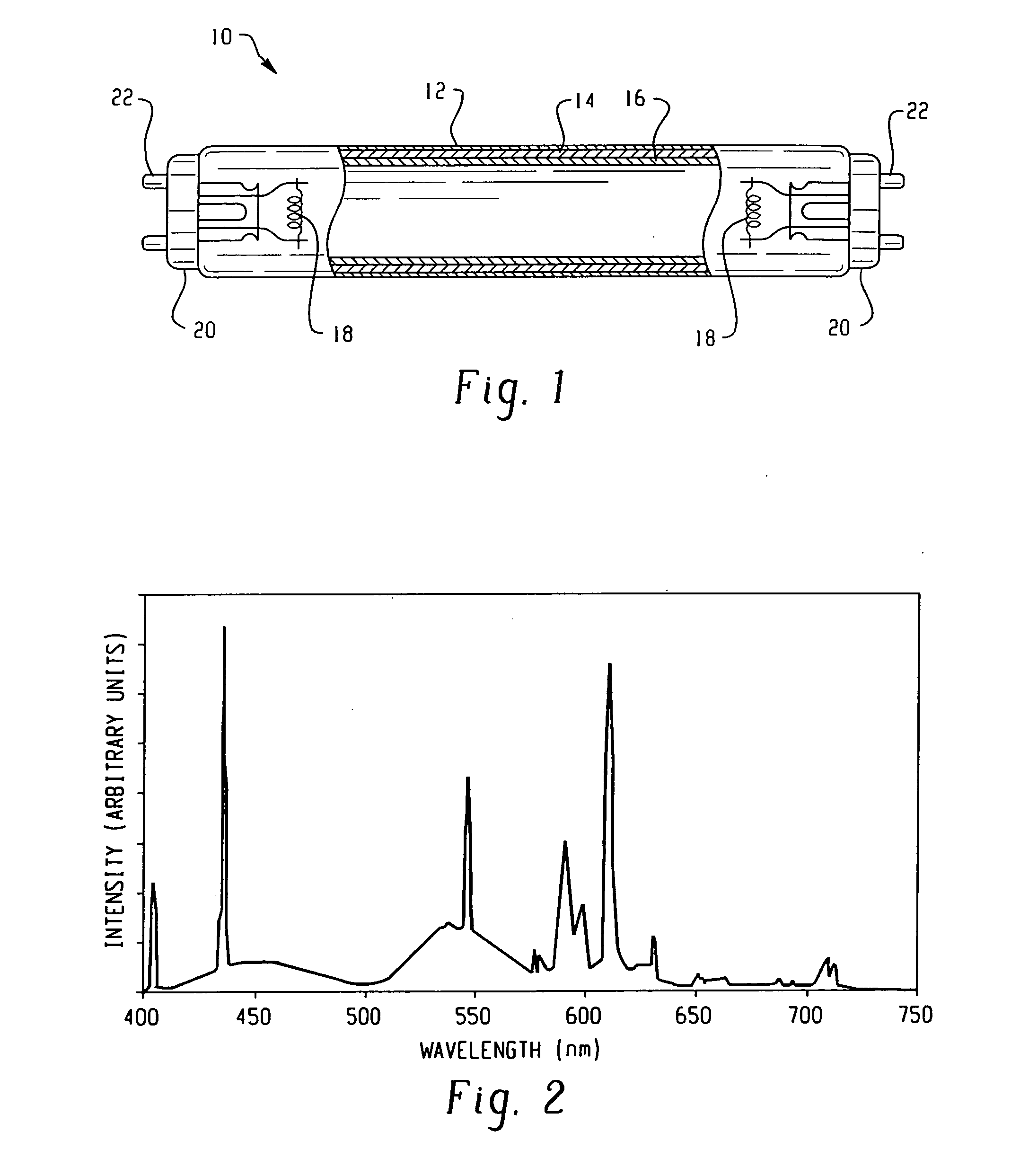
[0073] A lamp having a CRI of 75 may be prepared using a phosphor blend comprising BaMgAl10O17:Eu2+, Zn2SiO4:Ge4+,Mn2+, (Y,In)BO3:Eu3+, and Y2O3:Eu2+. The resulting emission spectra of the blend is shown in FIG. 2. The resulting lamp had a calculated luminosity at 4100 K that was 2.6% greater than a lamp having a CRI of 83 prepared using a known tri-phosphor blend comprising BaMgAl10O17:Eu2+, LaPO4:Ce3+,Tb3+, and Y2O3:Eu3+.

example 2

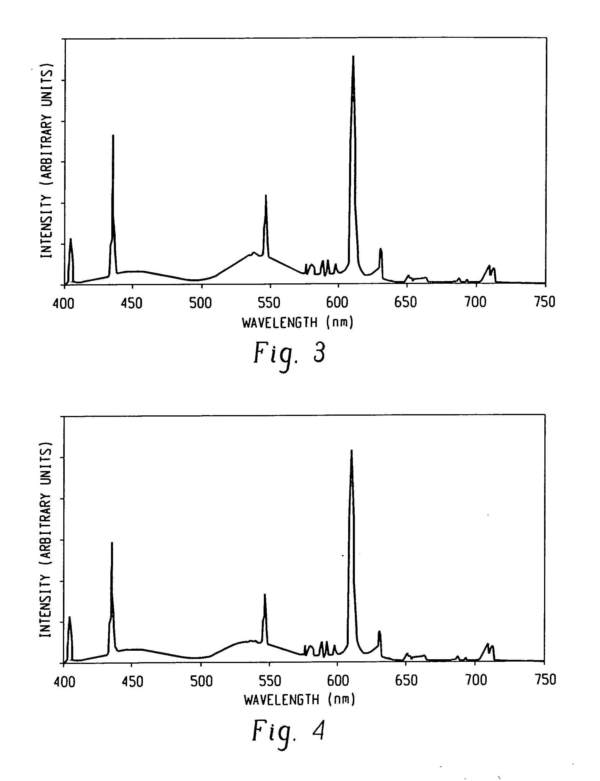
[0074] A lamp having a CRI of 82.5 may be prepared using a phosphor blend comprising BaMgAl10O17:Eu2+, Zn2SiO4:Ge4+,Mn2+, and Y2O3:Eu2+. The resulting emission spectra of the blend is shown in FIG. 3. The resulting lamp had a calculated luminosity at 4100 K that was 1.8% greater than a lamp having a CRI of 83 prepared using a known tri-phosphor blend comprising BaMgAl10O17:Eu2+, LaPO4:Ce3+,Tb3+, and Y2O3:Eu3+.

example 3

[0075] A lamp having a CRI of 87 may be prepared using a phosphor blend comprising BaMgAl10O17:Eu2+, Zn2SiO4:Ge4+, Mn2+, Y2O3:Eu2+, and BaMgAl10O17:Eu2+,Mn2+. The resulting emission spectra of the blend is shown in FIG. 4. The resulting lamp had a calculated luminosity at 4100 K that was 1.7% lower than a lamp having a CRI of 83 prepared using a known tri-phosphor blend comprising BaMgAl10O17:Eu2+, LaPO4:Ce3+,Tb3+, and Y2O3:Eu3+. It is well known that at higher CRI values, there is an inherent tradeoff between luminosity and CRI. Thus, although the lamp having a CRI of 87 has a slightly lower lumen output compared to the known tri-phosphor lamp, it has a higher CRI and the reduced luminosity is actually superior to other known lamps having such a high CRI.


PUM


Abstract

A fluorescent lamp including a phosphor layer comprising a phosphor blend including four or more optimized phosphors emitting within a specific spectral range to optimize luminosity for a given color rendering index (CRI) and color coordinated temperature (CCT). The blend will include at least four phosphors selected from the following: a blue phosphor having an emission peak at 440-490 nm, a blue-green phosphor having an emission peak at 475-525 nm, a green phosphor having an emission peak at 515-550 nm, an orange phosphor having an emission peak from 550-600 nm, a deep red phosphor having an emission peak at 615-665 nm, and a red phosphor having an emission peak at 600-670 nm.

Description

FIELD OF INVENTION [0001] The present invention relates to phosphor compositions, particularly phosphors for use in fluorescent lamps. More particularly, the present invention relates to improving the efficacy of a fluorescent lamp by providing an optimized blend of four or more phosphors for use therein. BACKGROUND OF THE INVENTION [0002] Fluorescent lamps typically have a transparent glass envelope enclosing a sealed discharge space containing an inert gas and mercury vapor. When subjected to a current provided by electrodes, the mercury ionizes to produce radiation having primary wavelengths of 185 nm and 254 nm. This ultraviolet radiation, in turn, excites phosphors on the inside surface of the envelope to produce visible light which is emitted through the glass. [0003] Generally, a fluorescent lamp for illumination uses a phosphor which absorbs the 254 nm Hg-resonance wave and is activated so as to convert the ultraviolet luminescence of mercury vapor into visible light. Conven...

Claims


Application Information

Patent Timeline
IPC IPC(8): C09K11/08C09K11/66C09K11/67C09K11/68C09K11/71C09K11/77H01J61/44
CPCC09K11/0838H01J61/44C09K11/0855C09K11/0877C09K11/661C09K11/664C09K11/666C09K11/67C09K11/681C09K11/715C09K11/7734C09K11/7739C09K11/774C09K11/7774C09K11/7777C09K11/778C09K11/7784C09K11/7786C09K11/7792C09K11/7794C09K11/7797C09K11/0844
Inventor SOULES, THOMASBEERS, WILLIAMGRECI, MICHAELSETLUR, ANANTCOMANZO, HOLLYMANIVANNAN, VENKATESANSRIVASTAVA, ALOK
Owner GENERAL ELECTRIC CO
Why Eureka
Try Eureka