
Planar light source device and liquid crystal display apparatus having the same

a light source device and liquid crystal display technology, applied in lighting and heating devices, cathode-ray/electron beam tube circuit elements, instruments, etc., can solve the problems of increasing volume, weight and manufacturing cost, etc., of lcd apparatus, and channeling, so as to prevent channeling and enhance the uniformity of luminance

Inactive Publication Date: 2005-08-18
SAMSUNG DISPLAY CO LTD
View PDF6 Cites 23 Cited by
  • Summary
  • Abstract
  • Description
  • Claims
  • Application Information

AI Technical Summary

Benefits of technology

[0008] The present invention provides a light source device capable of preventing channeling to enhance uniformity of luminance. The present invention also provides an LCD apparatus having the above-mentioned light source device.
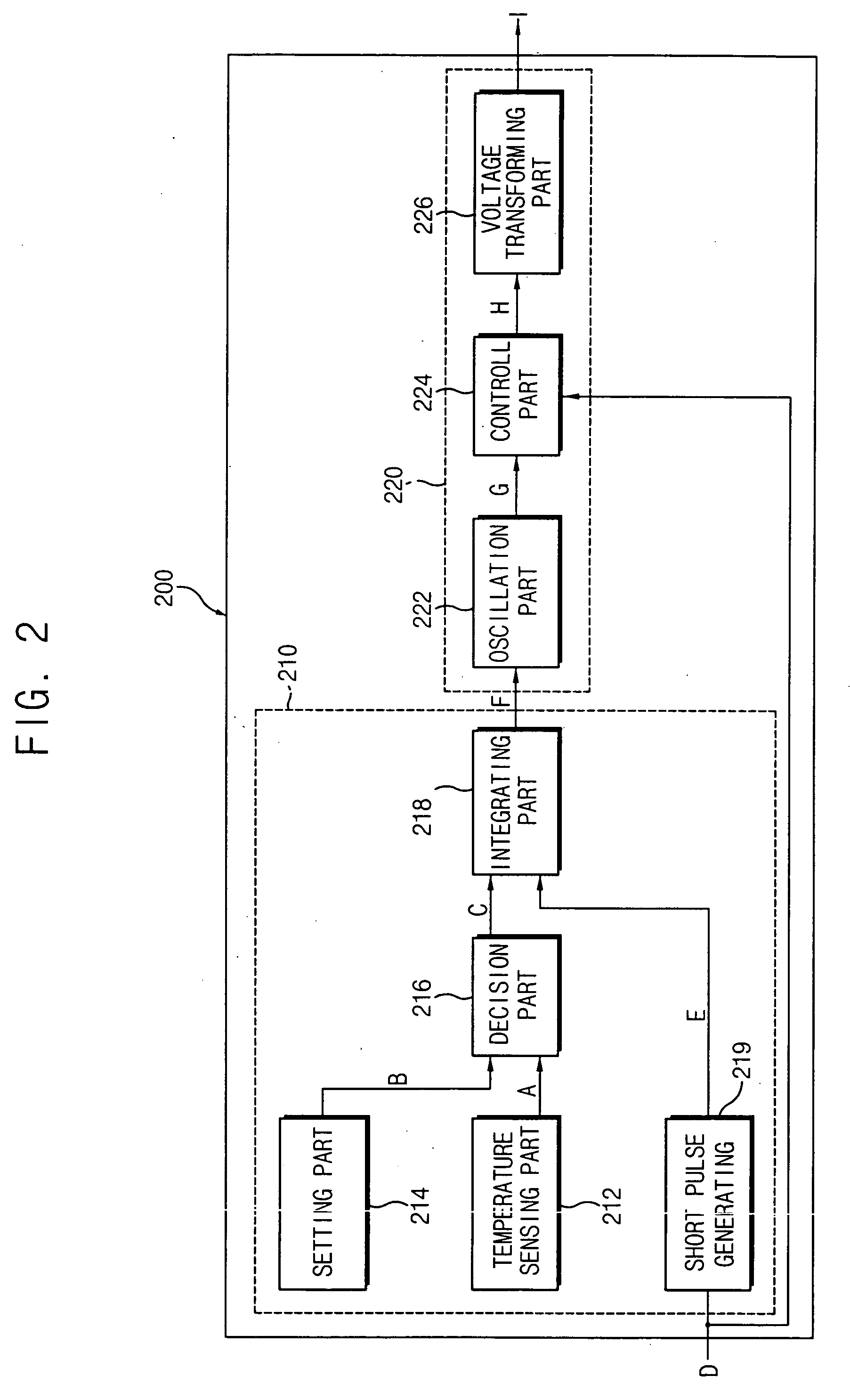
[0011] According to the present invention, channeling that induces deterioration of display quality is prevented by adjusting operating frequency. That is, when the environmental temperature is lower than a temperature that corresponds to a temperature that induces channeling under a conventional operating frequency, the operating frequency is lowered and gradually increased, thereby preventing channeling.

Problems solved by technology

The additional components, however, also increase volume, weight and manufacturing cost, etc., of the LCD apparatus.
However, when the discharge spaces are connected to each other, channeling is induced due to a cross talk between the discharge spaces.

Method used


Image

  • Planar light source device and liquid crystal display apparatus having the same
  • Planar light source device and liquid crystal display apparatus having the same
  • Planar light source device and liquid crystal display apparatus having the same

Examples


Embodiment Construction

[0025] It should be understood that the exemplary embodiments of the present invention described below may be modified in many different ways without departing from the inventive principles disclosed herein, and the scope of the present invention is therefore not limited to these particular flowing embodiments. Rather, these embodiments are provided so that this disclosure will be thorough and complete, and will fully convey the concept of the invention to those skilled in the art by way of example and not of limitation.

[0026] Hereinafter, the embodiments of the present invention will be described in detail with reference to the accompanied drawings.

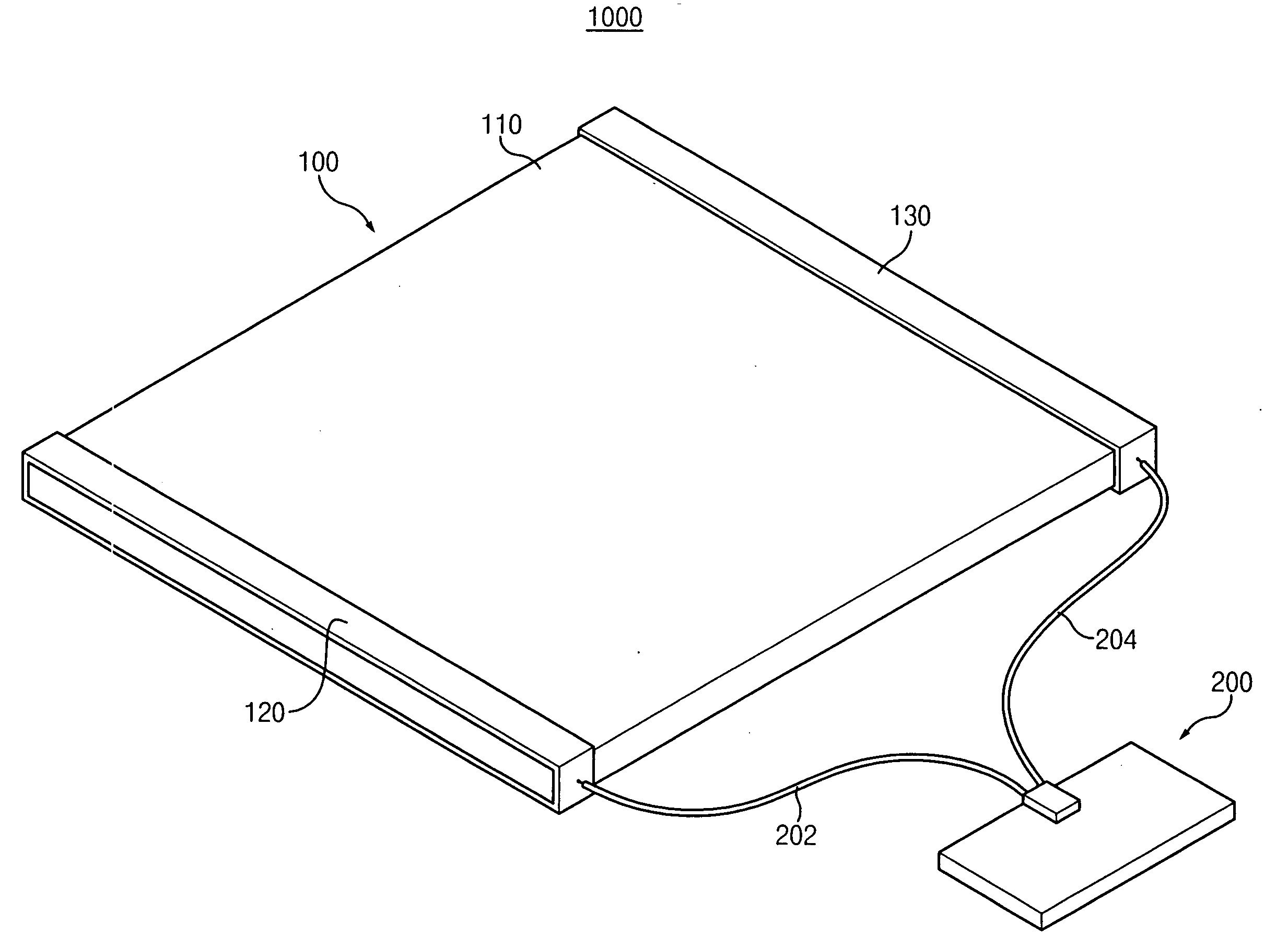
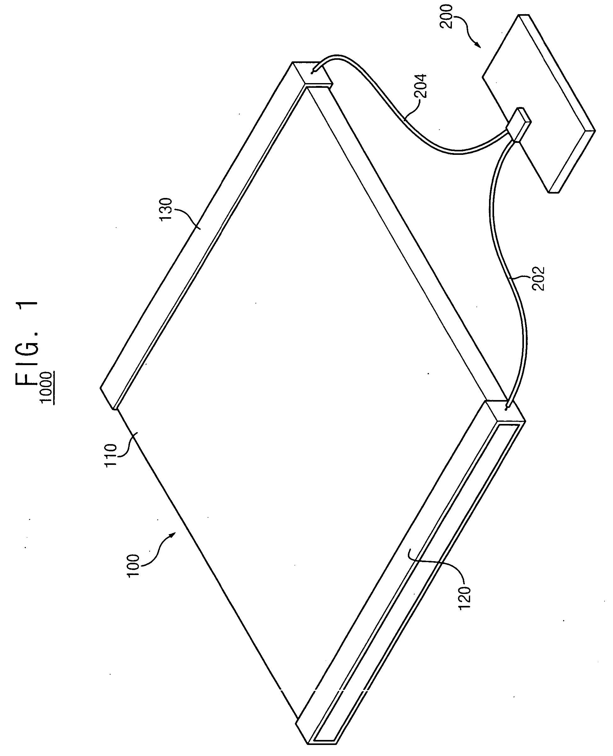
[0027]FIG. 1 is a perspective view illustrating a planar light source device according to an exemplary embodiment of the present invention.

[0028] Referring to FIG. 1, a planar light source device 1000 according to the present embodiment includes a planar light source 100 that generates light and a driver circuit 200 that drives the pl...


PUM

PropertyMeasurementUnit
temperatureaaaaaaaaaa
driving voltageaaaaaaaaaa

Abstract

An LCD apparatus includes a light source generating light, a driver circuit and an LCD panel. The driver circuit includes a driving voltage control section and a driving voltage generating section. The driving voltage control section senses an environmental temperature and outputs a control signal having a level which is adjusted based on a comparison of the environmental temperature to a reference temperature. The driving voltage generating section is electrically connected to the driving voltage control and generates a driving voltage based on the control signal. The LCD panel displays an image by using the light generated from the light source. Channeling that induces deterioration of display quality is prevented by adjusting an operating frequency of the light source according to the environmental temperature.

Description

BACKGROUND OF THE INVENTION [0001] 1. Field of the Invention [0002] The present invention relates to a planar light source device, and more particularly to a liquid crystal display apparatus having the planar light source device. [0003] 2. Description of the Related Art [0004] A liquid crystal display (LCD) apparatus is a flat type display apparatus displaying images using liquid crystal. The LCD apparatus has many merits including, for example, thin thickness, lightweight, low power consumption, low driving voltage, etc., making the LCD apparatus popular for use in various fields. [0005] Since the LCD apparatus itself does not emit light, the LCD apparatus employs a light source that provides light to the LCD apparatus. An example of a typical light source employed by the LCD apparatus is a conventional backlight assembly. The conventional backlight assembly employs either a cold cathode fluorescent lamp (CCFL) that generates linear light or a light emitting diode (LED) that genera...

Claims


Application Information

Patent Timeline
Patent Type & Authority Applications(United States)
IPC IPC(8): G02F1/13357G02F1/133G02F1/1335G02F1/136G09G3/34G09G3/36H01J61/30H01J61/56H01J65/00H05B37/02H05B41/24
CPCG02F1/133602G09G3/3406H01J61/56G09G2320/041G09G2320/0233G06K7/10881H04M1/21
Inventor JANG, HYEON-YONG
Owner SAMSUNG DISPLAY CO LTD
Learn More